
Project Overview
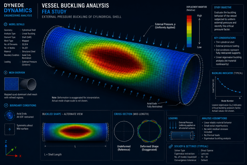
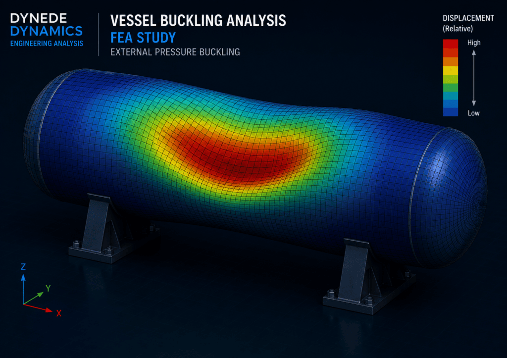
This finite element analysis study examines the buckling behaviour of a thin-walled cylindrical pressure vessel subjected to external static pressure.
Pressure vessels and similar cylindrical structures can be vulnerable to structural instability when external pressure produces compressive stresses within the shell. Unlike conventional yielding, buckling may occur suddenly when the structural stiffness of the shell is no longer sufficient to maintain its original geometry.
The purpose of the study is to investigate the characteristic instability behaviour of the vessel and identify the deformation modes associated with loss of structural stability.
The analysis demonstrates how FEA can be used to examine buckling behaviour in pressure vessels, tanks, cylindrical shells, subsea components and similar thin-walled structures.
Analysis Objective
The objective of the analysis is to investigate the vessel’s susceptibility to buckling under external pressure and identify the characteristic deformation modes that may develop as the structure approaches instability.
Thin-walled cylindrical structures can be particularly sensitive to compressive loading. Depending on the geometry and support conditions, structural instability may become important before conventional material strength limits govern the design.
The assessment considers:
- Cylindrical vessel geometry
- Shell thickness and structural stiffness
- Material properties
- External pressure loading
- Vessel support conditions
- Global shell deformation
- Characteristic buckling modes
- Regions susceptible to structural instability
The resulting buckling modes provide insight into the way the vessel may deform if its structural stability is exceeded.
FEA Model & Boundary Conditions
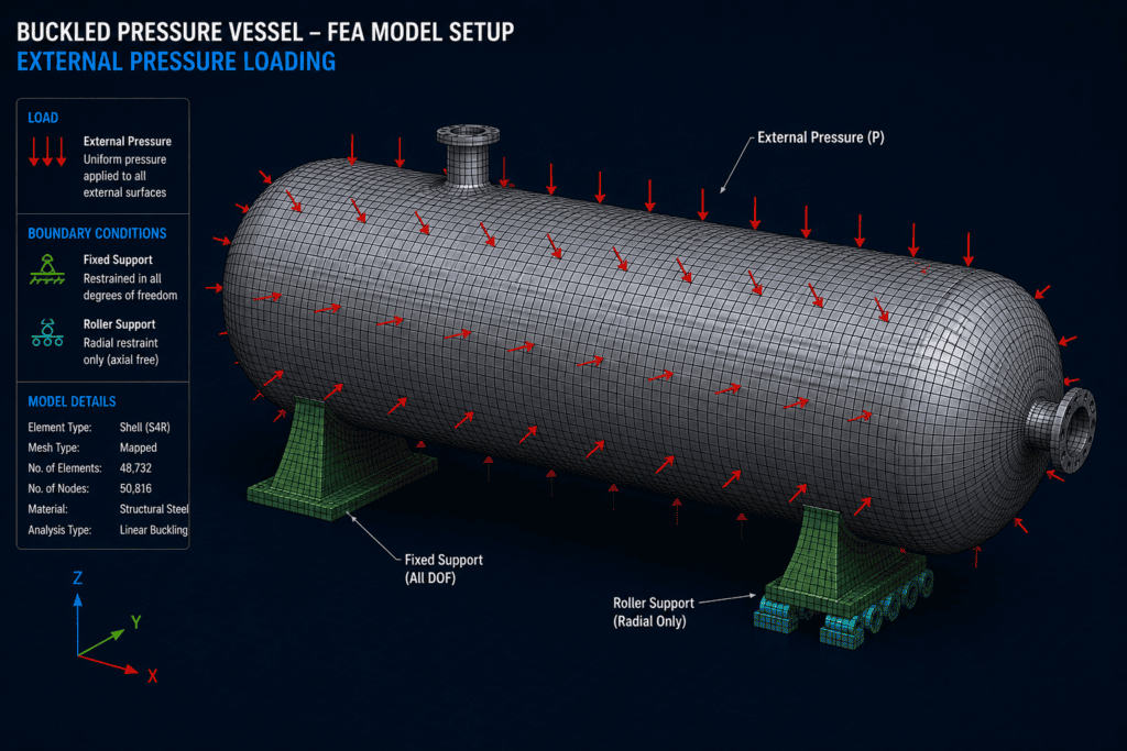
A three-dimensional finite element model is developed to represent the cylindrical vessel and its principal structural features.
The model captures the overall shell geometry required to investigate global instability while retaining sufficient detail to represent the structural response of the vessel.
Material properties are assigned to represent the vessel construction, and appropriate constraints are applied to reproduce the intended support conditions.
External pressure is applied across the relevant vessel surfaces to produce the compressive shell loading responsible for the buckling response.
Boundary conditions require careful consideration because excessive restraint can artificially increase structural stiffness, while insufficient restraint may introduce unrealistic rigid-body behaviour.
The model therefore considers:
- Vessel shell geometry
- End geometry
- Representative support locations
- Material properties
- External pressure loading
- Structural constraints
- Appropriate load application
- Relevant shell behaviour
The resulting model provides the basis for investigating the stability characteristics of the vessel.
Mesh & Analysis Approach
The vessel is discretised using a finite element mesh suitable for representing the deformation behaviour of the cylindrical shell.
Mesh quality is particularly important in buckling analysis because the predicted instability modes depend on the ability of the model to reproduce changes in shell curvature and deformation across the structure.
The mesh is therefore developed to provide appropriate resolution across the cylindrical surface and around geometric transitions.
The analysis examines the structural response of the vessel and identifies characteristic buckling mode shapes associated with instability.
These mode shapes should not be interpreted in the same way as conventional displacement results from a static structural analysis. Instead, they indicate characteristic patterns in which the structure is susceptible to losing stability.
Buckling Behaviour & Results
The FEA results reveal characteristic deformation patterns associated with instability of the cylindrical vessel wall.
As structural stability is lost, the initially circular shell can develop circumferential and longitudinal deformation patterns rather than maintaining its original cylindrical form.
The resulting buckling mode provides a visual indication of where the shell is most susceptible to instability and how the deformation may develop across the vessel.
The distribution of deformation is more important than simply considering the largest displayed displacement because buckling mode shapes are principally used to understand the form of structural instability.
The analysis can therefore provide insight into:
- Location of instability within the vessel shell
- Circumferential buckling behaviour
- Longitudinal deformation patterns
- Influence of supports and end conditions
- Relative susceptibility of different regions
- Characteristic structural mode shapes
This information provides a useful basis for engineering assessment of the vessel’s stability behaviour.
Interpretation of Buckling Modes
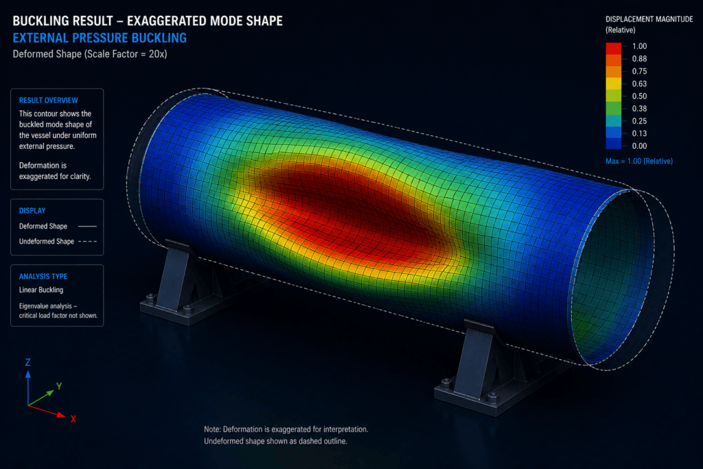
Buckling analysis may produce several possible instability modes.
The lowest modes are generally of greatest interest because they represent the structural patterns associated with the earliest predicted loss of stability within the idealised model.
Higher modes may show different combinations of circumferential lobes, longitudinal waves or localised deformation.
Reviewing several modes can therefore help establish whether the predicted instability is dominated by a single global deformation pattern or whether several similar modes are possible.
The mode shape itself is particularly useful for identifying the regions of the structure that warrant closer engineering investigation.
Engineering Considerations
Buckling behaviour can be strongly influenced by factors that may have relatively little effect on a conventional linear stress analysis.
These include:
- Vessel diameter-to-thickness ratio
- Overall vessel length
- Shell thickness
- Material stiffness
- End geometry
- Support arrangement
- Stiffening features
- Geometric imperfections
- Manufacturing tolerances
- Loading distribution
Real fabricated vessels are not geometrically perfect. Small deviations in roundness, welding distortion, dimensional tolerances and other imperfections can influence the actual buckling resistance of a thin shell.
For this reason, an eigenvalue buckling analysis is particularly useful for identifying likely instability modes and providing an initial assessment of structural behaviour, but the predicted result should be interpreted within the assumptions of the model.
Where greater confidence is required, further assessment may include nonlinear analysis, geometric imperfections, sensitivity studies or comparison with applicable engineering design requirements.
Role of Nonlinear Analysis
A linear buckling analysis provides an efficient method of identifying characteristic instability modes and estimating the structural behaviour of an idealised vessel.
However, real buckling behaviour can involve geometric nonlinearity, changing stiffness and sensitivity to initial imperfections.
A more detailed nonlinear analysis may therefore be appropriate where the behaviour close to collapse is important or where the vessel operates in conditions for which buckling is a significant design consideration.
The buckling mode obtained from the initial analysis can also provide useful information for defining representative geometric imperfections in a subsequent nonlinear model.
This creates a logical progression from initial stability assessment to more detailed structural investigation when required.
Engineering Outcome
The study demonstrates how finite element analysis can be used to investigate structural instability in a thin-walled pressure vessel subjected to external pressure.
The predicted buckling modes provide insight into the deformation patterns that may develop as structural stability is lost and highlight regions of the vessel that may require further assessment.
A properly developed buckling model can help engineers:
- Identify characteristic instability modes
- Understand global shell behaviour
- Locate regions susceptible to buckling
- Examine the influence of boundary conditions
- Assess the effect of structural geometry
- Support more detailed nonlinear investigation
- Provide technical evidence for engineering assessment
- Improve understanding of structural stability
The analysis therefore provides more than a visual representation of a deformed vessel. It provides an engineering basis for understanding how and where instability may develop.
FEA Buckling Analysis
Dynede Dynamics provides finite element analysis for mechanical components and structures where structural stability forms an important part of the engineering assessment.
Buckling analysis can be applied to pressure vessels, cylindrical shells, tanks, structural members and other components subjected to compressive loading.
Typical capabilities include:
- Linear eigenvalue buckling analysis
- Structural stability assessment
- Buckling mode identification
- Shell deformation assessment
- Mesh refinement studies
- Boundary-condition assessment
- Static structural analysis
- Nonlinear analysis where appropriate
- Engineering interpretation of FEA results
- Technical reporting and documentation
Discuss Your Engineering Requirements
If you require buckling analysis of a pressure vessel, cylindrical shell or other structure subjected to compressive loading, Dynede Dynamics can provide FEA support from model development and loading definition through analysis, interpretation and technical reporting.
To discuss your FEA requirements or a specific structural stability problem, please [contact Dynede Dynamics].