
Project Overview
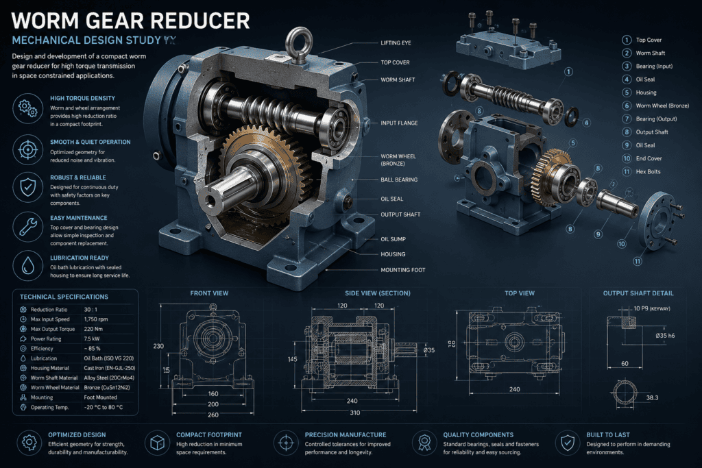
This mechanical design study explores the development of a compact worm gear reducer intended to provide high torque transmission and speed reduction within a relatively small mechanical package. The assembly combines a worm shaft, bronze worm wheel, output shaft, bearings, seals and a rigid housing into an integrated gearbox suitable for demanding mechanical applications.
The study focuses on component arrangement, shaft support, housing configuration, lubrication, assembly access and manufacturability. Particular attention is given to creating a practical reducer that provides reliable operation while remaining straightforward to manufacture, assemble and maintain.
Design Requirements
The reducer is required to transmit rotational power between perpendicular shafts while reducing input speed and increasing available output torque. The mechanical arrangement must provide adequate support for the worm shaft and output shaft while maintaining accurate alignment between the mating gear components.
The design must also provide suitable mounting interfaces, effective lubrication, bearing and seal locations, adequate structural rigidity and access for assembly and maintenance. Compact overall dimensions are desirable without compromising component strength or serviceability.
Gear Reduction Arrangement
The central feature of the assembly is the worm-and-wheel transmission. Rotation of the worm shaft drives the larger worm wheel mounted on the output shaft, producing a substantial reduction in rotational speed together with a corresponding increase in output torque.
The geometry and relative positioning of these components are important to achieving consistent tooth contact and smooth operation. Shaft centre distances, gear alignment and bearing positions must therefore be controlled carefully within the housing.
The selected arrangement also provides a compact method of transmitting motion between shafts positioned approximately perpendicular to one another.
Worm Shaft & Input Arrangement
The worm shaft forms the input side of the reducer and incorporates the worm geometry required to engage with the bronze worm wheel. The shaft is supported by bearings positioned to maintain alignment and resist the radial and axial forces generated during operation.
Shaft shoulders and bearing seats provide accurate component location, while the external end of the shaft can be configured to interface with a motor, coupling or other driving equipment.
Suitable transitions and fillets are incorporated between changes in shaft diameter to reduce local stress concentrations and improve manufacturability.
Worm Wheel & Output Shaft
The worm wheel is mounted securely on the output shaft and transfers the reduced-speed, higher-torque motion to the driven equipment. The output shaft must therefore provide sufficient torsional strength while maintaining accurate support within the gearbox housing.
A bronze worm wheel can provide favourable sliding and wear characteristics when operating against a hardened steel worm. The final material combination would be selected according to transmitted load, speed, lubrication conditions, duty cycle and required service life.
The output shaft may incorporate a keyway or other mechanical connection to transmit torque to an external coupling, pulley, sprocket or driven component.
Bearings, Seals & Shaft Support
Bearings are positioned around the input and output shafts to maintain accurate alignment while accommodating the loads generated by the gear mesh. Their arrangement must consider both radial loading and the axial thrust that can occur in worm gear systems.
Oil seals are incorporated where the shafts pass through the housing to retain lubricant and reduce the possibility of contamination entering the gearbox.
Correct bearing fits, shaft tolerances and housing bore dimensions are important to achieving reliable operation and controlling unwanted shaft movement.
Housing Design
The gearbox housing provides the primary structural support for the complete assembly. It maintains the relative positions of the worm shaft, worm wheel and bearings while also forming the enclosure required to retain the lubricant.
The housing geometry incorporates mounting feet, bearing locations, cover interfaces and sufficient internal clearance for the rotating components. Local wall thickness and reinforcement are considered around highly loaded regions to provide adequate stiffness without introducing unnecessary material.
A removable top cover provides access to the internal components for assembly, inspection and maintenance.
Lubrication & Thermal Considerations
Worm gear drives involve significant sliding contact between the mating tooth surfaces, making effective lubrication particularly important. The housing is therefore designed to accommodate an oil bath that provides continuous lubrication to the gear mesh during operation.
Lubricant selection would depend on operating speed, load, temperature and gear materials. Appropriate oil level, sealing and provision for filling and draining should also be considered during detailed design.
Because mechanical losses within the gear mesh can generate heat, the thermal behaviour of the reducer should be assessed for applications involving high loads or continuous operation.
Fits, Tolerances & Assembly
Dimensional control is required to maintain correct alignment between the worm and worm wheel. Bearing bores, shaft seats and housing interfaces therefore require appropriate tolerances to prevent excessive movement while still allowing practical assembly.
The assembly sequence should allow the worm shaft, output shaft, bearings, seals and gear components to be installed without unnecessary complexity. Removable covers and end plates can provide access to internal components while retaining the structural integrity of the housing.
Standard bearings, seals and fasteners should be used wherever practical to simplify manufacture, procurement and future maintenance.
Engineering Considerations
The performance of the reducer depends on several interacting factors including reduction ratio, transmitted torque, input speed, gear geometry, bearing loads, lubrication, thermal behaviour and housing stiffness.
Particular consideration should be given to the axial forces generated by the worm gear arrangement and their effect on the shaft and bearing system. Gear tooth contact, shaft deflection and housing deformation can also influence alignment and operating performance.
Further analytical work may therefore include shaft calculations, bearing-life assessment, gear contact analysis and FEA of the housing or other highly loaded components.
Manufacturability & Maintenance
The reducer is developed with practical manufacturing methods in mind. Shaft components can be produced using conventional turning and machining operations, while the housing may be manufactured as a casting followed by machining of critical bearing and mounting surfaces.
The use of accessible covers, standard fasteners and replaceable bearings and seals simplifies inspection and maintenance. The arrangement also allows worn components to be replaced without requiring replacement of the complete gearbox.
Manufacturing tolerances should be concentrated on functionally important interfaces rather than applied unnecessarily throughout the entire assembly.
Outcome & Next Steps
The resulting concept provides a compact and integrated worm gear reducer suitable as the basis for further mechanical development. The arrangement combines speed reduction, torque transmission, shaft support, lubrication and structural containment within a practical gearbox assembly.
Further development could include detailed gear calculations, efficiency assessment, shaft and bearing verification, thermal analysis, lubrication specification, tolerance definition and structural FEA of the housing. The design could then progress to detailed manufacturing drawings, bills of materials and complete assembly documentation.