
Project Overview
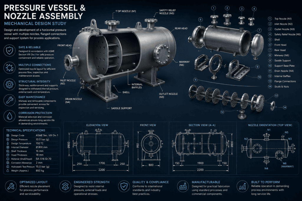
This mechanical design study explores the development of a horizontal pressure vessel and nozzle assembly intended for process and industrial applications. The design integrates the cylindrical shell, formed heads, process nozzles, flanged connections, manway, internal components and saddle supports into a complete mechanical assembly.
The study focuses on practical vessel configuration, pressure containment, nozzle positioning, structural support, fabrication and maintainability. Particular attention is given to coordinating the individual components so that the vessel can be manufactured, inspected, installed and serviced effectively while providing reliable operation under the specified design conditions.
Design Requirements
The vessel is required to safely contain pressurised fluid while providing the connections necessary for process inlet, outlet, drainage, pressure relief and inspection.
The design concept uses a horizontal cylindrical vessel supported by saddle assemblies. Multiple nozzles are positioned around the shell and heads according to their intended functions, while a flanged manway provides access to the vessel interior.
The design must also consider internal pressure, operating temperature, external loads, material selection, corrosion allowance, fabrication requirements and the mechanical loads introduced by connected piping and supporting structures.
Vessel Shell & Head Design
The cylindrical shell forms the principal pressure-containing section of the vessel. Its diameter and wall thickness are selected according to the required operating conditions, material properties, fabrication requirements and applicable pressure-vessel design rules.
Formed heads close the ends of the vessel and provide a structurally efficient transition from the cylindrical shell. The head geometry and thickness must be appropriate for the internal pressure and connected components.
The study image illustrates a nominal internal diameter of approximately 800 mm, with representative shell and head thicknesses of 16 mm and 18 mm respectively. These dimensions represent the design-study concept and would require detailed verification during final engineering.
Nozzle Arrangement & Connections
Several nozzles are incorporated into the vessel to provide the required process and service connections. These include inlet and outlet connections, a drain connection, top-mounted process connections and a dedicated safety-relief connection.
Nozzle positioning is considered in relation to process functionality, internal components, accessibility and connected pipework. Adequate spacing must be maintained between neighbouring openings and major structural features.
Flanged connections allow the vessel to interface with external piping and equipment while also facilitating assembly, inspection and maintenance.
Manway & Maintenance Access
A flanged manway is incorporated into the vessel to provide access to the internal space for inspection, cleaning and maintenance.
The manway location must provide practical personnel or service access while avoiding interference with saddles, nozzles and internal components. Its opening also represents a significant discontinuity in the pressure boundary and must therefore be considered during detailed mechanical assessment.
Removable bolted closures allow the vessel to be opened when required while maintaining pressure containment during normal operation.
Internal Components
Internal baffles or similar components may be incorporated where required by the process duty. These components can influence internal flow distribution, residence time, separation behaviour or structural support depending on the intended application.
Their arrangement must be coordinated with vessel nozzles and the manway so that installation and maintenance remain practical.
Internal attachments also introduce local loads into the vessel shell and should therefore be considered during detailed structural design.
Saddle Support Design
The horizontal vessel is supported by saddle assemblies positioned beneath the cylindrical shell. These supports transfer the vessel weight and operational loads into the supporting structure or foundation.
The saddle arrangement must consider the weight of the empty vessel, contained fluid, connected components and any additional operating loads. Local stresses can develop in the shell around the saddle locations, particularly for larger or more heavily loaded vessels.
Base plates and suitable mounting provisions are incorporated to provide stable installation and allow connection to the supporting structure.
Pressure & Structural Considerations
The vessel must maintain structural integrity under its specified internal design pressure and temperature. The concept illustrated in this study uses representative conditions of approximately 10 bar(g)1 design pressure and 150°C design temperature.
In addition to internal pressure, the mechanical design may need to consider vessel self-weight, contained-fluid weight, piping loads, nozzle loads, thermal expansion, lifting loads and other installation or operating conditions.
Detailed engineering would determine the required shell, head and nozzle thicknesses and assess local stresses around openings, supports and other geometric discontinuities.
Materials & Corrosion Allowance
Material selection depends on the operating environment, pressure, temperature, process fluid, fabrication requirements and applicable design standards.
The concept uses SA-516 Grade 70 for the shell and heads, a commonly used pressure-vessel plate material. A representative corrosion allowance of 2 mm is included to account for expected material loss during the vessel’s service life.
Final material selection and corrosion allowance would be determined from the actual process conditions and project specifications.
Nozzle Reinforcement & Local Stress
Openings introduced into a pressure-vessel shell interrupt the continuity of the pressure boundary and can produce local stress concentrations. Nozzle connections must therefore be assessed to determine whether additional reinforcement is required.
The evaluation may consider opening size, shell thickness, nozzle thickness, reinforcement geometry and external loads transmitted through connected piping.
For highly loaded or geometrically complex connections, local finite element analysis can be used to supplement conventional pressure-vessel calculations and investigate stress distributions around the nozzle region.
Fabrication & Welded Construction
The vessel is intended to be compatible with conventional pressure-vessel fabrication methods. The shell may be formed from rolled plate with welded longitudinal and circumferential seams, while formed heads, nozzles, flanges and support components are subsequently integrated into the assembly.
Weld locations should provide appropriate access for fabrication and inspection. The design should also minimise unnecessary geometric complexity where simpler fabrication methods can achieve the required performance.
Applicable welding procedures, inspection requirements and non-destructive examination would be established during detailed engineering and fabrication planning.
Inspection, Testing & Safety
Inspection and testing are important elements of pressure-vessel manufacture and commissioning. Welded joints and pressure-containing components may require visual inspection and appropriate non-destructive examination according to the applicable design and fabrication requirements.
A hydrostatic pressure test can be performed following fabrication to demonstrate the integrity of the completed pressure boundary. The study concept indicates a representative hydrostatic test pressure of approximately 15 bar(g).
The safety-relief nozzle provides a dedicated connection for protective equipment intended to prevent unacceptable vessel overpressure during operation.
Engineering Considerations
Pressure-vessel design requires several engineering disciplines to be considered together. Internal pressure determines much of the basic pressure-boundary geometry, while nozzle loads, supports, thermal effects and fabrication details can create important local stresses.
The position of nozzles, manways and supports should therefore be established as part of an integrated design rather than treating each feature independently.
Where required, conventional pressure-vessel calculations can be supplemented by FEA to investigate local stresses around nozzles, saddle supports, attachments and other areas where simplified analytical methods may not fully represent the structural behaviour.
Manufacturability & Maintenance
The vessel arrangement is developed with practical fabrication and long-term serviceability in mind. Standard flange arrangements, accessible bolted connections and conventional welded construction can simplify manufacturing and procurement.
The manway provides access to internal components, while nozzle placement should allow external piping to be installed and maintained without unnecessary obstruction.
Inspection access, drainage, lifting provisions and replacement of removable components should all be considered before the design progresses to manufacturing documentation.
Outcome & Next Steps
The resulting concept provides an integrated mechanical arrangement for a horizontal pressure vessel incorporating the principal pressure-containing components, process connections, maintenance access and structural supports.
Further development could include detailed code calculations, nozzle reinforcement assessment, flange and bolting verification, saddle-support analysis, piping-load evaluation and local FEA of critical regions. The design could then progress to detailed fabrication drawings, weld specifications, inspection requirements, bill of materials and manufacturing documentation.
- (g) means gauge pressure, e.g. 10 bar(g) = 10 bar above atmospheric pressure. 0 bar(g) = normal atmospheric pressure. In absolute terms, 10 bar(g) ≈ 11 bar(a), because atmospheric pressure is roughly 1 bar. ↩︎