
Structural Assessment of a Pressure Vessel Nozzle Connection
Pressure vessel nozzles introduce geometric discontinuities into the vessel shell and can produce significant localised stresses around the nozzle-to-shell junction. These regions require careful assessment, particularly where internal pressure is combined with external loads transferred through connected pipework or equipment.
This finite element analysis study demonstrates the assessment of a pressure vessel nozzle and surrounding reinforcement, with particular attention to stress distribution, local deformation and the influence of reinforcement geometry.
The objective is to identify critical regions within the connection and evaluate how changes to the reinforcement arrangement can improve structural performance while maintaining a practical and manufacturable design.
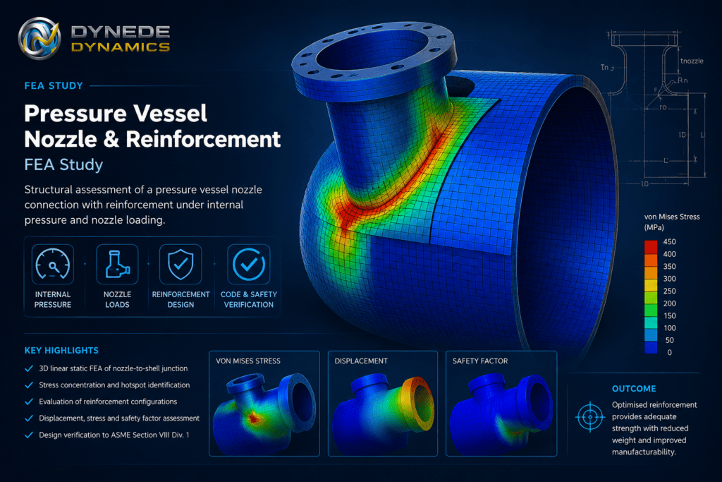
Engineering Challenge
A nozzle interrupts the otherwise continuous geometry of a pressure vessel shell. The opening, nozzle neck and associated reinforcement alter the load path through the vessel wall, resulting in local bending and elevated stresses around the junction.
The engineering challenge is therefore not simply to determine the overall stress in the vessel, but to understand how loads are transferred through the nozzle, shell and reinforcement.
The assessment considers the effects of:
- Internal pressure acting on the vessel and nozzle
- Local stress concentration around the shell opening
- Loads transferred through the nozzle connection
- Interaction between the nozzle neck and vessel shell
- Reinforcement geometry and load distribution
- Local deformation around the nozzle-to-shell junction
Finite element analysis provides a detailed view of these effects that complements conventional design calculations.
FEA Model Development
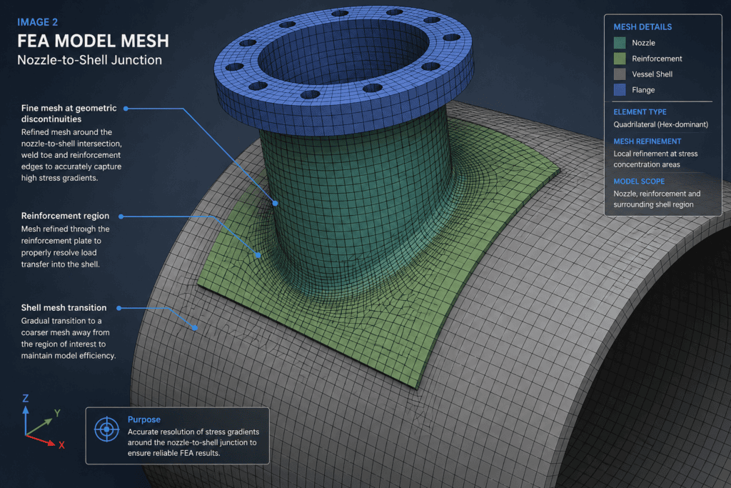
A three-dimensional finite element model was developed to represent the pressure vessel shell, nozzle and reinforcement region.
Particular attention was given to the nozzle-to-shell intersection because this is the principal region of interest. Mesh refinement can be concentrated around geometric transitions and other locations where high stress gradients are expected while using a more economical mesh away from the connection.
The modelling approach allows the structural behaviour of the complete junction to be examined rather than considering individual components independently.
Model considerations included:
- Representative vessel shell geometry
- Nozzle neck and opening geometry
- Reinforcement arrangement
- Appropriate material properties
- Internal pressure loading
- Representative nozzle loading
- Boundary conditions representing the surrounding vessel structure
- Local mesh refinement at critical geometric transitions
Mesh quality and refinement are particularly important around the nozzle junction to obtain meaningful local stress distributions.
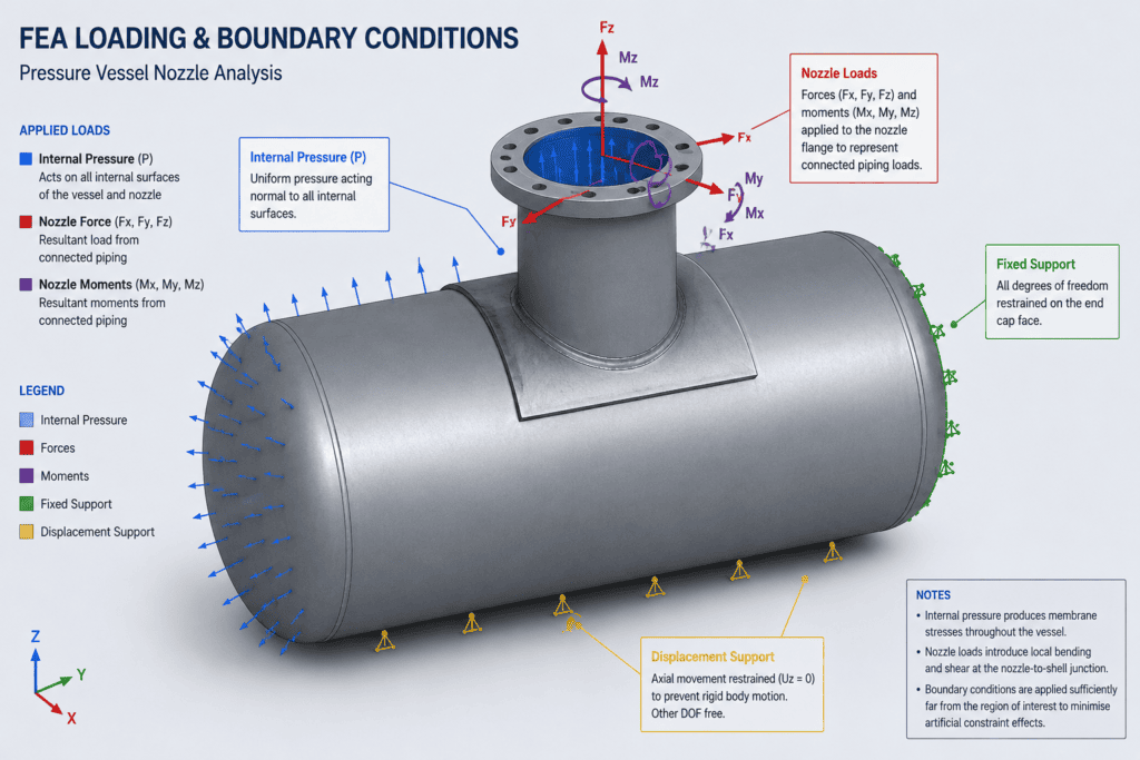
Loading and Boundary Conditions
Internal pressure produces membrane stresses throughout the vessel while also acting on the nozzle opening and connected geometry.
Additional nozzle forces and moments may arise from connected piping, thermal expansion, equipment loads or other external influences. These loads can introduce local bending into the nozzle and surrounding vessel wall.
For this study, the analysis methodology considers the combined structural response of the nozzle connection under representative pressure and nozzle loading.
Boundary conditions are selected sufficiently far from the region of interest to minimise artificial influence on the local behaviour of the nozzle junction.
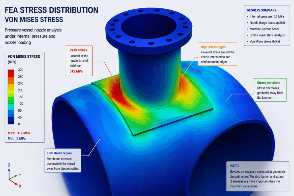
Stress Distribution
The FEA results allow the stress field around the complete nozzle connection to be visualised.
Elevated stresses are expected around geometric transitions where the nozzle intersects the vessel shell and where load paths change rapidly. Rather than relying solely on the maximum contour value, the distribution and extent of these stresses should be examined.
The assessment can distinguish between broad structural stress patterns and highly localised peaks associated with geometry, mesh behaviour or idealised modelling assumptions.
This provides a more useful basis for engineering judgement than simply reporting a single maximum stress value.
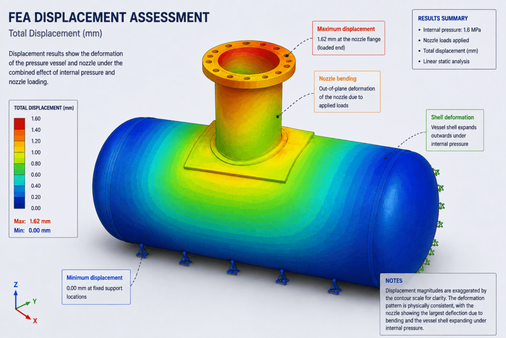
Displacement Assessment
Deformation results provide an additional indication of the stiffness and behaviour of the nozzle connection.
The displacement pattern can be reviewed to determine whether the nozzle and surrounding shell deform in a physically reasonable manner under the applied loading.
Excessive local flexibility may influence connected pipework, sealing arrangements or other components even where material stress remains acceptable.
Reviewing stress and displacement together therefore provides a more complete understanding of structural behaviour.
Reinforcement Assessment
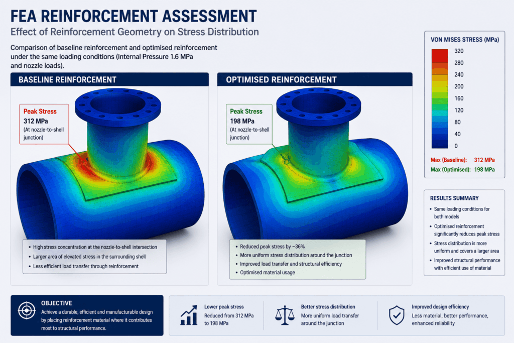
Reinforcement around a pressure vessel nozzle is intended to compensate for the interruption to the vessel shell and provide an effective load path around the opening.
FEA can be used to investigate how the reinforcement geometry influences:
- Stress distribution around the nozzle
- Local shell stiffness
- Load transfer between the nozzle and vessel
- Peak stress regions
- Structural efficiency
- Material usage
- Manufacturability
Alternative reinforcement arrangements can be compared before committing to fabrication.
The objective is not necessarily to add more material, but to place material where it contributes effectively to structural performance.
Design Optimisation
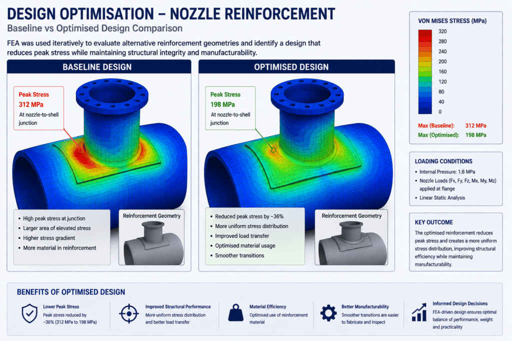
Once the baseline behaviour has been established, the model can be used to investigate potential design improvements.
Possible variables include reinforcement dimensions, local thickness, transition geometry and nozzle proportions.
Each modification can be evaluated against the same loading conditions, allowing the effect on stress distribution and deformation to be assessed directly.
This iterative approach enables FEA to become part of the design process rather than simply a final verification exercise.
Engineering Outcome
The study demonstrates how finite element analysis can provide detailed insight into the behaviour of a pressure vessel nozzle connection.
By identifying the principal load paths and areas of elevated stress, the analysis supports informed decisions regarding reinforcement geometry and local structural design.
A well-developed FEA model can help engineers:
- Identify critical stress regions
- Understand nozzle-to-shell load transfer
- Evaluate local deformation
- Compare reinforcement concepts
- Reduce unnecessary material
- Improve structural efficiency
- Support subsequent design verification
The result is a better-informed design in which structural performance, weight and manufacturability can be considered together.
FEA for Pressure Vessel Components
Dynede Dynamics provides finite element analysis and engineering assessment for mechanical components, structures and pressure-containing equipment.
Analysis can be integrated with mechanical design and optimisation activities, allowing potential structural issues to be identified and addressed during development rather than after a design has been finalised.
Typical capabilities include:
- Linear static finite element analysis
- Stress and deformation assessment
- Local stress investigation
- Mesh refinement and convergence studies
- Load-path assessment
- Design comparison
- Structural optimisation
- Engineering interpretation of analysis results
- Technical reporting and documentation
Discuss Your Engineering Requirements
If you require structural analysis of a pressure vessel component, nozzle connection or other mechanically loaded assembly, Dynede Dynamics can provide FEA support from initial model development through analysis, interpretation and design refinement.