
Structural Assessment of a Loaded Mechanical Bracket
Mechanical brackets are widely used to transfer loads between components, frames and supporting structures. Although their geometry may appear relatively simple, changes in section thickness, mounting locations, holes and geometric transitions can create localised areas of elevated stress.
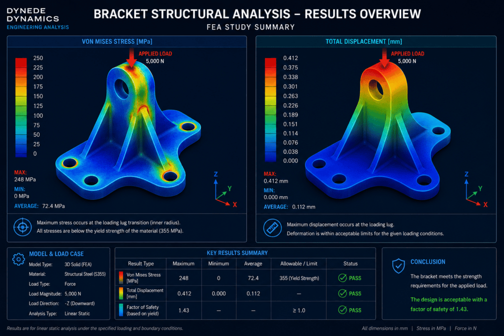
This finite element analysis study demonstrates the structural assessment of a mechanically loaded bracket, with particular attention to stress distribution, deformation and the transfer of load between the applied load location and the mounting points.
The objective of the analysis is to understand the structural response of the bracket under representative loading and identify areas requiring closer engineering assessment.
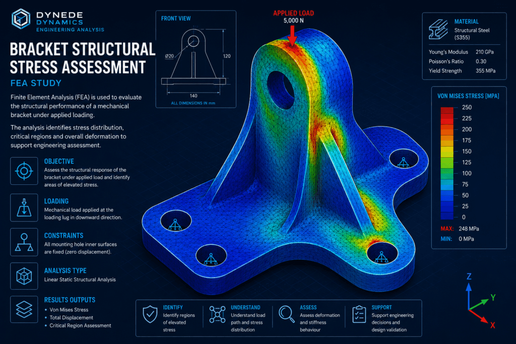
Engineering Challenge
The bracket is required to transfer an applied mechanical load into a supporting structure through its mounting points.
The load path passes through several changes in geometry, including mounting holes, curved transitions and changes in cross-section. These features can introduce local stress concentrations that may not be apparent from simple hand calculations.
The engineering assessment therefore considers:
- Overall stress distribution within the bracket
- Stress concentrations around mounting holes
- Stress around geometric transitions and fillets
- Load transfer between the loaded region and mounting points
- Overall deformation of the component
- Structural behaviour under the applied loading
Finite element analysis provides a practical method of examining the complete component and understanding how the geometry responds to the applied load.
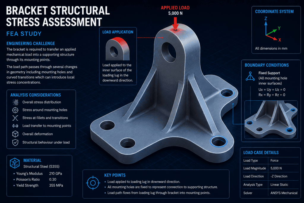
FEA Model Development
A three-dimensional finite element model is developed to represent the bracket geometry.
The model includes the principal structural features that influence stiffness and load transfer, including mounting holes, supporting sections and relevant geometric transitions.
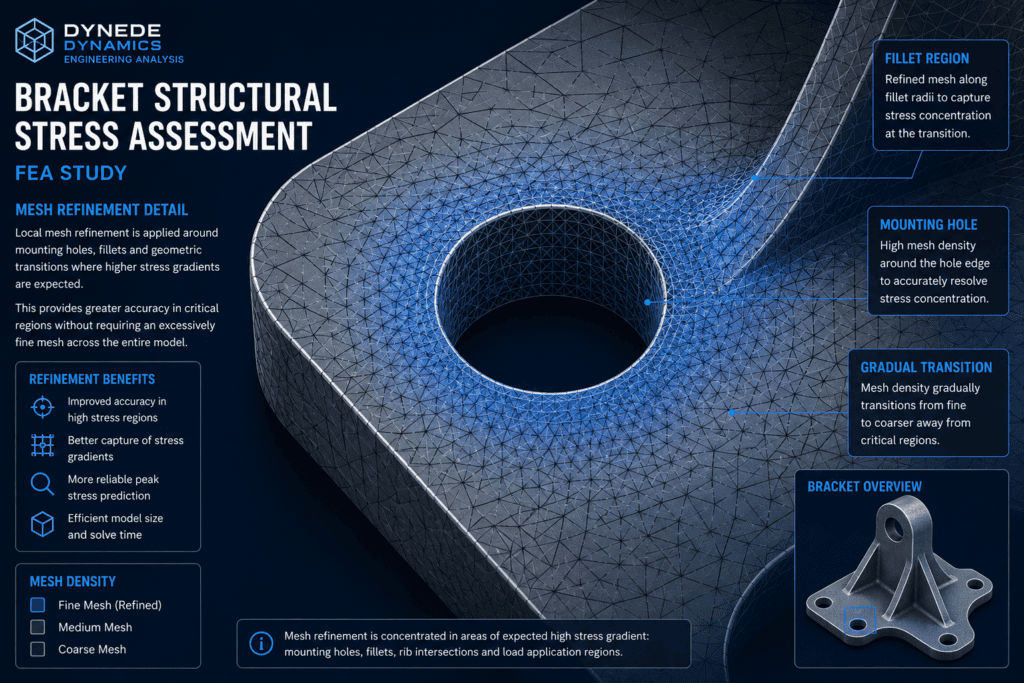
The finite element mesh is refined in areas where higher stress gradients are expected, particularly around mounting holes, fillets and regions where the load is introduced.
The model considers:
- Representative bracket geometry
- Appropriate material properties
- Mounting and support locations
- Applied mechanical loading
- Relevant contact or connection assumptions
- Local mesh refinement around critical features
The purpose of the model is to reproduce the structural behaviour of the component sufficiently accurately to allow meaningful engineering interpretation of the results.
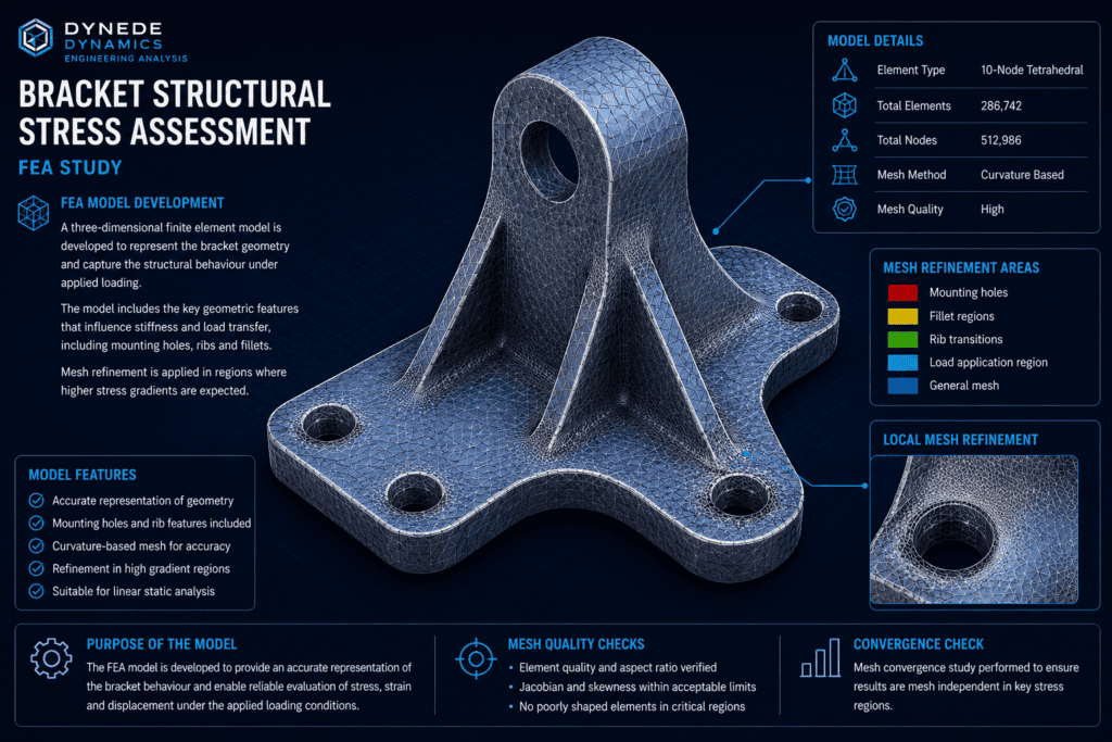
Loading and Boundary Conditions
Appropriate loading and boundary conditions are essential for obtaining meaningful FEA results.
The bracket is constrained at its mounting locations to represent its connection to the supporting structure. A representative mechanical load is then applied at the appropriate load-transfer region.
The boundary conditions are selected to reproduce the intended physical behaviour of the component without unnecessarily restricting deformation.
The analysis considers the resulting load path from the point of application through the bracket and into its mounting locations.
This allows the relationship between the applied load, bracket stiffness and local structural response to be examined.
Mesh Assessment
Mesh density has an important influence on the accuracy and interpretation of finite element results.
A relatively coarse mesh may be suitable in regions where the stress field changes gradually, while additional refinement is required around geometric discontinuities and areas of higher stress gradient.
For the bracket model, particular attention is given to:
- Mounting holes
- Fillet regions
- Changes in section geometry
- Load application regions
- Areas of elevated stress
Local refinement provides greater resolution in these areas without requiring an unnecessarily fine mesh throughout the entire component.
The resulting mesh provides an appropriate basis for examining the overall structural response and local stress behaviour.
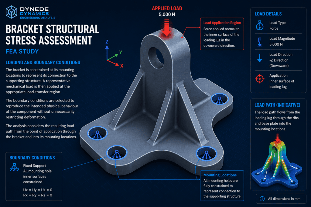
Stress Distribution
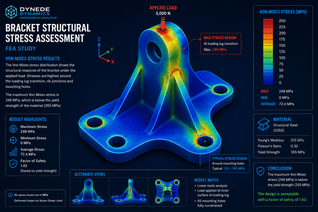
The finite element results show how stress is distributed throughout the bracket under the applied loading.
The majority of the component may experience relatively moderate stress, while higher stresses can develop around mounting holes, fillets and other geometric transitions.
The von Mises stress contour provides a clear visual representation of these regions and helps identify the principal areas requiring engineering attention.
Particular care is taken when interpreting very localised maximum values. A single peak value does not necessarily represent the behaviour of the surrounding structure.
Instead, the stress distribution, stress gradient and extent of the elevated-stress region are considered together.
Displacement Assessment
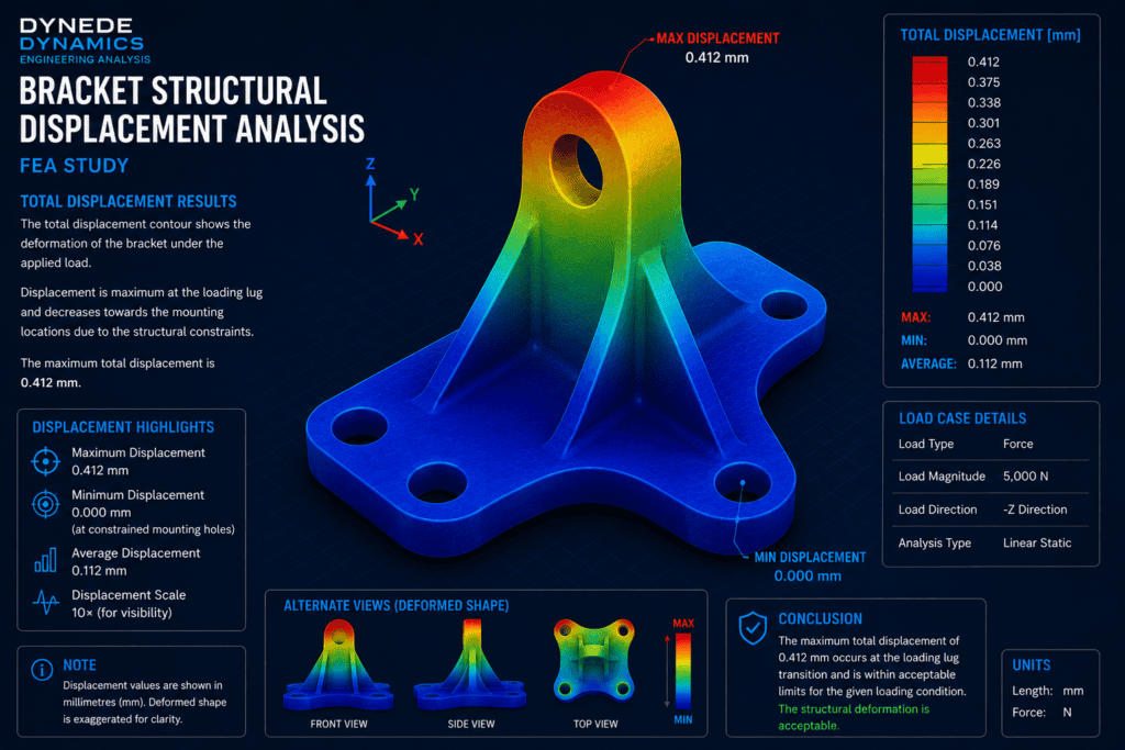
Displacement results provide an important additional view of the bracket’s structural behaviour.
The deformation pattern shows how the component responds globally to the applied load and helps confirm that the predicted behaviour is physically reasonable.
Maximum displacement would normally be expected towards the loaded region, with movement reducing towards the constrained mounting locations.
Reviewing displacement results can help determine whether the bracket provides sufficient stiffness for its intended function.
The displacement pattern should therefore be considered alongside the stress results rather than treating either result independently.
Critical Region Assessment
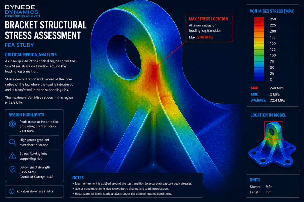
Areas of elevated stress identified by the overall analysis can be examined in greater detail.
For a mechanical bracket, these regions commonly occur around mounting holes, fillet transitions or locations where the load path changes direction.
A local assessment helps determine whether the elevated stress represents a broader structural condition or a highly localised peak.
The engineer can examine:
- Stress magnitude
- Stress gradient
- Size of the affected region
- Relationship to nearby geometric features
- Mesh density in the region
- Local deformation behaviour
This provides a more meaningful interpretation of the FEA results than relying only on the maximum value reported by the analysis software.
Engineering Interpretation
Finite element analysis produces detailed numerical results, but those results require engineering interpretation.
Stress contours, displacement plots and maximum values must be considered in relation to the component geometry, loading assumptions, material properties and boundary conditions used in the model.
For this bracket assessment, the analysis provides an understanding of:
- How the applied load travels through the component
- Where the highest structural stresses occur
- How the mounting regions respond to loading
- Whether deformation follows the expected physical behaviour
- Which areas require closer engineering attention
The analysis therefore provides a structured basis for assessing the mechanical behaviour of the bracket.
Engineering Outcome
The FEA study demonstrates how finite element analysis can be used to assess the structural behaviour of a mechanically loaded bracket.
The analysis identifies the principal load path, areas of elevated stress and the overall deformation pattern of the component.
By examining the complete stress field rather than relying solely on a single maximum value, the engineer can develop a clearer understanding of how the bracket responds to its operating loads.
The study provides useful information for:
- Structural assessment
- Identification of critical regions
- Stress and deformation evaluation
- Assessment of mounting regions
- Engineering review of component behaviour
- Supporting subsequent design verification
The principal purpose of the analysis is to provide engineering insight into the structural response of the component.
FEA for Mechanical Components
Dynede Dynamics provides finite element analysis for mechanical components, assemblies and engineering structures.
FEA can support engineering assessment during product development, investigation of existing designs or verification of components subjected to mechanical loading.
Typical capabilities include:
- Linear static finite element analysis
- Stress assessment
- Deformation assessment
- Mesh refinement and convergence studies
- Local stress investigation
- Load-path assessment
- Mechanical component analysis
- Engineering interpretation of FEA results
- Technical reporting and documentation
Discuss Your Engineering Requirements
If you require finite element analysis of a mechanical component, bracket, support or other loaded structure, Dynede Dynamics can provide FEA support from model development and loading definition through analysis, results interpretation and technical reporting.
To discuss your FEA requirements or a specific engineering challenge, please [contact Dynede Dynamics].