
Flow Distribution Assessment of an Industrial Manifold
Flow manifolds are widely used in piping systems, process equipment, hydraulic circuits and industrial machinery where a single incoming flow must be distributed between several downstream branches. Although the geometry can appear relatively simple, the internal flow may not divide uniformly between the outlets.
Changes in flow direction, differences in branch position and interaction between the main flow and individual outlets can produce unequal velocity distributions, local pressure variations, separation and recirculation.
Computational Fluid Dynamics (CFD) provides a practical method of visualising these effects throughout the manifold and assessing how effectively the geometry distributes flow between the branches.
This study considers a representative manifold consisting of a single inlet supplying multiple outlet branches. The objective is to investigate the internal flow behaviour and identify geometric features that influence outlet-to-outlet flow distribution.
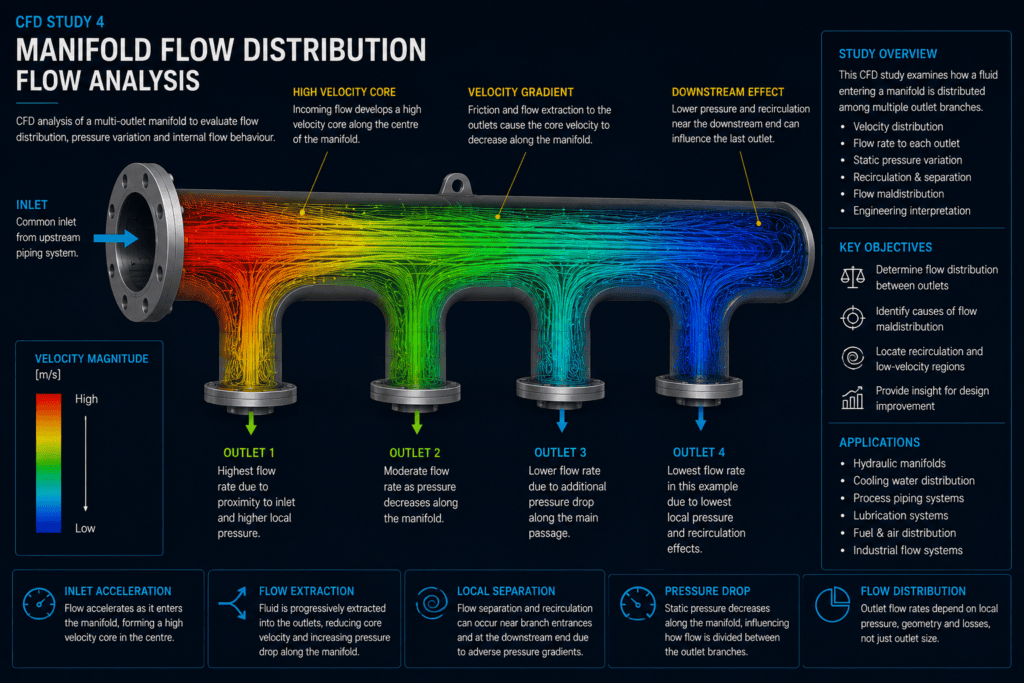
Industrial flow manifold showing CFD velocity field and streamlines from a single inlet through multiple outlet branches
Project Overview
The manifold receives fluid through a common inlet and distributes it through a series of outlet branches positioned along the main body.
Ideally, each branch would receive the required proportion of the total flow. In practice, however, the momentum of the incoming fluid and the pressure field within the manifold can cause some branches to receive more flow than others.
Branches located close to the inlet may behave differently from those farther downstream, while the geometry at each junction can introduce local separation and secondary flow.
The CFD study therefore examines the complete internal flow field rather than assuming that the incoming flow divides equally between the outlets.
Analysis Objectives
The principal objective is to assess the hydraulic behaviour of the manifold and determine how effectively the inlet flow is distributed between the outlet branches.
The CFD assessment considers:
- Velocity distribution through the main manifold
- Flow division between individual outlets
- Static-pressure variation along the manifold
- Local acceleration around branch entrances
- Separation and recirculation near junctions
- Flow behaviour near the downstream end of the manifold
- Regions contributing to outlet-to-outlet maldistribution
- Opportunities for improving the internal geometry
The results provide a basis for understanding whether the manifold geometry promotes balanced flow or produces preferential flow through particular branches.
CFD Model Development
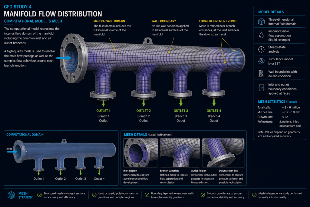
For internal-flow CFD analysis, the computational domain represents the fluid volume contained within the manifold and its branches.
The internal flow passage is extracted from the representative manifold geometry to create a continuous fluid domain extending from the common inlet to each individual outlet.
The principal geometric features influencing the flow are retained, including the main manifold passage, branch entrances and outlet passages. External details that do not influence the internal fluid behaviour can be excluded from the computational model.
This approach concentrates the analysis on the geometry directly responsible for pressure distribution and flow division.
Boundary Conditions
A representative inlet condition is applied at the entrance to the manifold, while appropriate outlet conditions are defined at each branch.
The internal surfaces of the manifold are treated as wall boundaries.
Fluid enters through the common inlet, travels along the main passage and progressively divides between the outlet branches. The resulting distribution is determined by the interaction between fluid momentum, pressure variation and the resistance associated with the individual flow paths.
For a project-specific analysis, the boundary conditions would be selected to represent the actual operating system. These could include specified inlet flow rate, inlet pressure, outlet pressures or other system-dependent conditions.
The present study focuses on the CFD methodology and characteristic flow behaviour rather than claiming performance values for a particular manufactured manifold.
Mesh Strategy
The computational domain is discretised using a three-dimensional CFD mesh suitable for resolving the overall manifold flow and the more complex behaviour occurring around individual branch junctions.
Local mesh refinement is particularly useful near the branch entrances, where the fluid changes direction and velocity gradients may become comparatively large.
Additional refinement may be applied near the inlet, downstream end region and locations where flow separation or recirculation is expected.
Appropriate near-wall treatment is also considered according to the turbulence model and the required level of solution accuracy.
A suitable mesh allows the global distribution between outlets to be predicted while retaining sufficient local resolution to investigate the mechanisms responsible for maldistribution.
Velocity Distribution
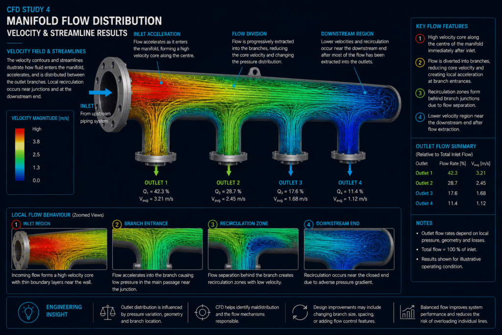
The velocity field illustrates how the incoming flow develops as it travels through the manifold.
Immediately downstream of the inlet, the fluid possesses significant axial momentum. As flow is progressively diverted into the branches, the velocity within the main passage changes and the internal pressure field adjusts accordingly.
At each branch entrance, part of the main flow must turn from the manifold into the outlet passage. This produces local three-dimensional behaviour that cannot always be represented accurately by assuming uniform velocity across the manifold.
Velocity contours can therefore identify regions of acceleration, low velocity and non-uniform flow approaching individual outlets.
Outlet Flow Distribution
One of the principal results of a manifold CFD analysis is the comparison of flow behaviour between the individual outlet branches.
Even when the outlets have identical nominal dimensions, they do not necessarily receive identical flow. Their position relative to the inlet and the pressure distribution along the main manifold can influence the amount of fluid entering each branch.
CFD allows the flow through each outlet to be evaluated independently and compared with the desired distribution.
Where significant maldistribution is identified, the results can help determine whether modifications to branch geometry, spacing, manifold dimensions or internal flow-control features should be investigated.
Separation & Recirculation
Changes in direction at the branch junctions can create local separation and recirculation.
These regions may occur near sharp geometric transitions, around the downstream side of branch entrances or near the closed end of the main manifold, depending on the configuration and operating condition.
Recirculation does not necessarily indicate that a design is unacceptable, but extensive low-velocity regions may contribute to additional hydraulic losses or undesirable flow behaviour.
Streamline visualisation provides a useful means of understanding these three-dimensional structures and identifying how fluid moves between the main passage and individual branches.
Static Pressure Distribution
The static-pressure field is closely related to the resulting outlet flow distribution.
As fluid travels through the manifold, pressure changes occur because of wall friction, changes in velocity, branch extraction and local losses associated with the junction geometry.
The pressure available at each branch entrance therefore depends on its position within the manifold and on the behaviour of the upstream flow.
Examining the complete pressure field helps explain why apparently identical outlets may experience different flow conditions.
Pressure and velocity results should consequently be interpreted together when assessing manifold performance.
Engineering Interpretation
The CFD results demonstrate that successful manifold design involves more than simply connecting several equal-diameter branches to a common pipe.
The internal pressure field, incoming momentum, branch geometry and manifold proportions collectively determine how the flow is distributed.
For engineering applications, CFD studies of this type can support investigation of:
- Outlet-to-outlet flow balance
- Branch diameter and geometry
- Branch spacing
- Manifold diameter
- Inlet configuration
- Pressure-loss reduction
- Recirculation and stagnant regions
- Alternative manifold layouts
- Flow-balancing features
The required distribution does not always need to be equal. Some systems intentionally require different flow rates through different branches. CFD can therefore be used to assess the geometry against the required distribution for the particular application.
Engineering Results Overview
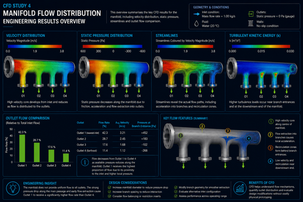
Velocity, pressure and streamline results provide complementary information about the hydraulic behaviour of the manifold.
Velocity contours reveal how the incoming flow develops and divides between the branches. Static-pressure contours help explain the driving pressure available at different outlet locations, while streamlines show the actual three-dimensional paths followed by the fluid.
Outlet results can then be compared to determine whether the distribution is sufficiently balanced for the intended application.
Together, these results provide a clear representation of the relationship between manifold geometry, internal pressure distribution and outlet flow balance.
Engineering Considerations
CFD predictions should be interpreted in the context of the modelling assumptions and boundary conditions used.
The predicted outlet distribution can be particularly sensitive to the way downstream conditions are represented. Assuming identical outlet pressures, for example, represents a different physical system from one in which each branch is connected to equipment with different downstream resistance.
Mesh resolution, turbulence modelling, fluid properties and convergence behaviour should also be considered when quantitative predictions are required.
For design verification, additional operating conditions may be investigated to determine whether acceptable distribution is maintained across the required operating range rather than at a single flow condition.
Outcome & Next Steps
This study demonstrates how CFD can be used to investigate flow distribution within a multi-outlet manifold and identify the mechanisms responsible for hydraulic maldistribution.
The analysis provides insight into velocity development, pressure variation, branch flow behaviour and local recirculation throughout the internal passage.
Where the initial configuration does not provide the required outlet distribution, the CFD model can be used to evaluate alternative branch arrangements, manifold dimensions or flow-balancing features before physical modifications are made.
The methodology can also be extended to headers, distribution pipes, hydraulic manifolds, cooling circuits and other multi-branch flow systems.
Discuss Your Engineering Requirements
Dynede Dynamics provides CFD analysis for manifolds, piping systems, valves, heat exchangers and other internal-flow equipment, from computational-domain development and meshing through to flow-distribution assessment and engineering interpretation.
Discuss your CFD or fluid-flow requirements with Dynede Dynamics to determine an appropriate analysis approach for your application.