
DESIGN OPTIMISATION STUDY 2 – PARAMETRIC THICKNESS OPTIMISATION
Reducing Component Mass While Maintaining Structural Performance
Parametric optimisation provides a practical method of improving an existing engineering design without fundamentally changing its architecture.
Rather than generating an entirely new material distribution, selected geometric parameters are varied within controlled limits and the resulting designs are evaluated against consistent structural criteria.
In this study, the thickness of key structural features within a representative mounting bracket is investigated to determine whether component mass can be reduced while maintaining acceptable stiffness, stress levels and overall structural integrity.
The objective is not simply to produce the lightest possible component. Instead, the study aims to identify a balanced design in which material is used more efficiently without compromising the functional requirements of the bracket.
Project Overview
The starting point for the study is a conventional aluminium mounting bracket designed to transfer an applied load from an upper lug interface into four mounting locations at the base.
The component consists of a base plate, twin upper load-transfer lugs and structural ribs connecting the loaded region to the mounting structure.
The baseline design provides a robust structural solution, but some regions may contain more material than is necessary for the specified loading condition.
A parametric study is therefore used to investigate the effect of reducing selected structural thicknesses.
Unlike topology optimisation, the fundamental component architecture remains unchanged. The mounting locations, lug geometry, load-transfer interfaces and overall structural arrangement are preserved throughout the study.
This allows material reduction to be investigated while maintaining a conventional and readily controllable engineering geometry.
Study Objective
The objective of the study is to:
- Reduce component mass
- Maintain adequate structural stiffness
- Maintain acceptable stress levels
- Preserve critical functional interfaces
- Retain a practical manufacturing geometry
- Identify a balanced thickness configuration for further development
1. BASELINE DESIGN
The baseline component establishes the reference geometry against which all subsequent design variants are compared.
The principal structural features of the bracket include:
- Four-hole mounting base
- Twin upper load-transfer lugs
- Machined lug bores
- Structural ribs connecting the lug region to the base
- Reinforced transitions between the ribs and mounting structure
- Fillets at major structural intersections
The baseline geometry is analysed using a defined material model, loading condition and set of boundary conditions.
These conditions remain unchanged throughout the parametric study so that differences in structural response can be attributed to the geometric changes being investigated.
Selection of Design Variables
Only selected dimensions are treated as optimisation variables.
For this study, the principal parameters are the base thickness, rib thickness and lug thickness.
Base Thickness
The base provides the primary connection between the structural ribs and the mounting locations.
Its thickness influences the stiffness of the mounting structure and the way load is distributed between the ribs and mounting points.
Reducing the base thickness can decrease component mass, but excessive reduction may increase local deformation or stress around the mounting regions.
Rib Thickness
The ribs form the principal structural members connecting the upper load-transfer region to the base.
Their thickness has a direct influence on component stiffness and the ability of the bracket to transfer load efficiently.
Reducing rib thickness can provide useful mass savings, but the resulting change in stress and deformation must be evaluated.
Lug Thickness
The upper lugs form the primary load-transfer interface.
Their thickness influences local stiffness and the stress distribution surrounding the lug bores.
Because this is a critical functional region, changes to lug thickness should be controlled carefully.
Preserved Geometry
Not every dimension is varied during optimisation.
Critical functional geometry remains fixed throughout the study, including:
- Mounting-hole locations
- Lug bore diameter and position
- Load application location
- Mounting interfaces
- Critical assembly interfaces
- General component architecture
Preserving these features ensures that each design variant remains compatible with the same surrounding system.
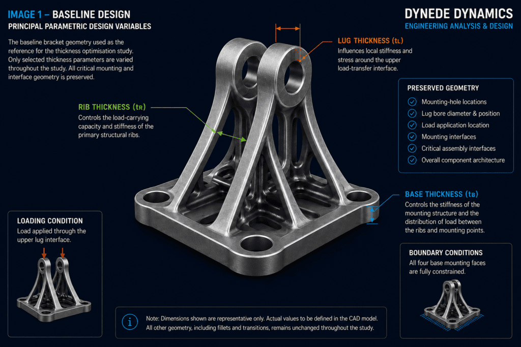
Baseline bracket showing the principal parametric design variables: base thickness, rib thickness and lug thickness. Critical mounting and lug interfaces are identified as preserved geometry.
2. PARAMETRIC DESIGN VARIANTS
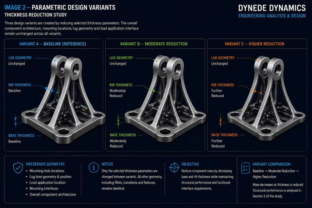
A small number of controlled geometry variants are created by modifying the selected thickness parameters.
The purpose of the study is not simply to make every structural feature as thin as possible.
Reducing thickness decreases material volume and therefore component mass, but it can also increase deformation and local stress.
The study therefore investigates the relationship between material reduction and structural performance.
Three representative configurations are considered.
Variant A — Baseline
The first configuration uses the original component dimensions.
This design provides the reference mass, stress and deformation behaviour against which the modified configurations are compared.
No geometric optimisation is applied to this variant.
Variant B — Moderate Thickness Reduction
The second configuration introduces a controlled reduction in selected base and rib thicknesses.
The critical mounting and load-transfer interfaces remain unchanged.
This configuration represents a conservative lightweighting strategy intended to remove material while retaining a geometry close to the baseline design.
Variant C — Higher Thickness Reduction
The third configuration introduces a greater reduction in selected structural thicknesses.
This variant is used to investigate whether further material removal continues to provide an effective weight saving or begins to produce an excessive structural penalty.
The same overall component architecture is retained.
Controlled Geometry Development
The resulting variants remain visually similar because the underlying design concept does not change.
This is an important characteristic of parametric optimisation.
Instead of replacing an established component architecture, the method investigates whether individual dimensions within that architecture can be improved.
The approach is particularly useful where:
- Functional interfaces are already established
- Manufacturing processes favour conventional geometry
- Packaging constraints limit major geometric changes
- Existing component architecture is already effective
- A controlled and easily documented optimisation process is required
3. STRUCTURAL ANALYSIS
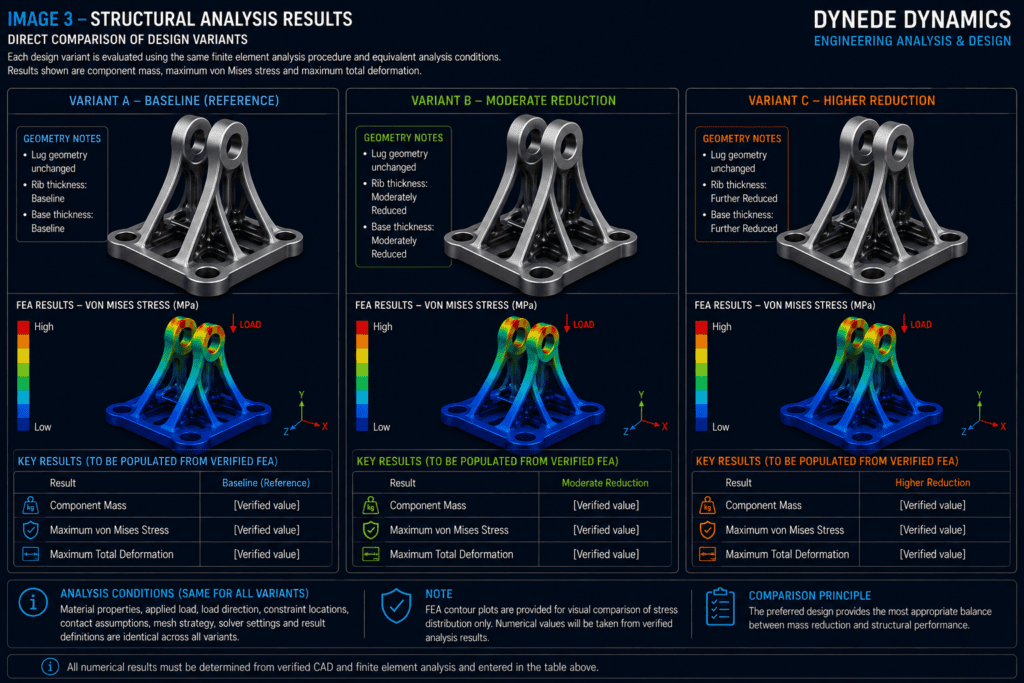
Each design variant is evaluated using the same finite element analysis procedure.
Maintaining equivalent analysis conditions is essential for producing a meaningful comparison.
Where practical, each configuration should use the same:
- Material properties
- Applied load
- Load direction
- Constraint locations
- Contact assumptions
- Mesh strategy
- Solver settings
- Result definitions
The structural response of each design can then be compared directly.
The principal quantities considered are component mass, von Mises stress and total deformation.
Where suitable design allowables are available, an appropriate safety factor or design margin can also be considered.
Applied Loading
The service load is applied through the upper lug interface.
The load is transferred from the lug region through the structural ribs and into the base before reaching the constrained mounting locations.
The same load magnitude, direction and application method are used for every design variant.
This prevents changes in loading assumptions from influencing the comparison between configurations.
Boundary Conditions
The mounting interfaces represent the connection between the bracket and the supporting structure.
Equivalent boundary conditions are applied to every configuration.
Maintaining identical boundary conditions ensures that the structural response of each design is evaluated on a consistent basis.
Material
The same material model is used throughout the study.
This ensures that differences in component mass and structural response result from changes in geometry rather than changes in material properties.
4. STRUCTURAL PERFORMANCE CRITERIA
Several engineering quantities are reviewed when comparing the design variants.
No single result should be considered in isolation.
The preferred design should provide an appropriate balance between mass reduction and structural performance.
Component Mass
Component mass is calculated from the geometric volume and material density.
Reducing base and rib thickness decreases material volume and therefore component mass.
The mass of each variant is compared with the baseline to determine the percentage reduction achieved.
A lower mass is desirable, but only where the resulting structural behaviour remains suitable for the intended application.
von Mises Stress
Equivalent von Mises stress is used to examine the stress distribution within each configuration.
Particular attention is given to regions where loads change direction or pass between structural features, including:
- Lug regions
- Rib-to-lug transitions
- Rib-to-base transitions
- Mounting regions
- Local fillets and geometric transitions
Reducing structural thickness can increase stress because the same applied load must be carried through a smaller cross-sectional area.
The stress distribution must therefore be reviewed for each design variant.
Total Deformation
Total deformation provides an indication of the overall stiffness of the component.
As structural members become thinner, deformation would generally be expected to increase.
The optimisation objective is therefore not necessarily to minimise deformation.
Instead, the objective is to ensure that the lighter component retains sufficient stiffness for its intended function.
Design Margin
Where verified material properties, loading requirements and allowable limits are available, an appropriate design margin or safety factor can also be evaluated.
The final acceptance criteria should be based on the actual engineering requirements of the component.
5. COMPARISON OF DESIGN VARIANTS
The analysis results are compared to determine the relationship between thickness reduction, component mass and structural response.
A controlled reduction in thickness may produce a useful mass saving with only a relatively small change in stress or deformation.
However, continued material reduction will eventually produce diminishing engineering benefit.
Beyond a certain point, a relatively small additional mass saving may result in a disproportionately large increase in stress or deformation.
This relationship is central to parametric optimisation.
The preferred design is therefore not automatically the lightest configuration.
Instead, it is the configuration that provides the most appropriate balance between structural performance and material efficiency.
Design Comparison
| Design Configuration | Mass | Mass Reduction | Maximum Stress | Maximum Deformation | Assessment |
|---|---|---|---|---|---|
| Baseline | [Verified value] | — | [Verified value] | [Verified value] | Reference |
| Moderate Reduction | [Verified value] | [Verified %] | [Verified value] | [Verified value] | Review |
| Higher Reduction | [Verified value] | [Verified %] | [Verified value] | [Verified value] | Review |
The numerical values should be populated using verified CAD and finite element analysis results.
Values should not be estimated purely for presentation.
Interpreting the Results
The comparison should consider three questions.
How much mass has been removed?
A meaningful reduction in mass should justify the geometric changes introduced.
What structural penalty has resulted?
The effect of material reduction on stress and deformation should remain appropriate for the design requirements.
Does the modified geometry remain practical?
The design should continue to provide suitable feature thicknesses, transitions, accessibility and manufacturing characteristics.
The selected configuration should satisfy all three considerations.
6. DESIGN SELECTION
Following comparison of the analysed configurations, a preferred thickness combination can be selected.
The selected design should provide a suitable balance between:
- Reduced component mass
- Required structural stiffness
- Acceptable stress levels
- Adequate design margin
- Manufacturing practicality
- Geometric robustness
- Functional interface requirements
This selection process requires engineering judgement.
A configuration that produces the greatest mass reduction may not necessarily represent the best engineering solution.
For example, an aggressive reduction in rib thickness may produce only a small additional weight saving compared with a moderate design while causing a significantly larger increase in deformation.
In such a case, the moderate configuration may provide the better overall solution.
The final decision should therefore consider the complete structural response rather than mass alone.
7. FINAL OPTIMISED DESIGN
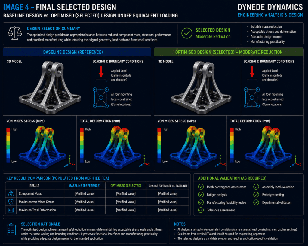
The selected design retains the fundamental architecture of the original bracket while using material more efficiently.
The upper load-transfer interface and mounting locations remain unchanged, allowing the component to perform the same fundamental function as the baseline design.
Material reduction is achieved through controlled modification of selected structural dimensions rather than extensive alteration of the component topology.
This provides several practical advantages.
Recognisable Design Architecture
The optimised component remains closely related to the original engineering design.
Its structural function can therefore be readily understood and reviewed.
Controlled Geometry
Critical dimensions remain explicitly defined within the CAD model.
The design does not depend on irregular or difficult-to-control optimisation surfaces.
Manufacturing Compatibility
Conventional ribs, surfaces, fillets and interfaces are retained.
This makes the design more compatible with conventional engineering manufacturing methods.
Direct Verification
Because the baseline and optimised designs use the same fundamental architecture and equivalent analysis conditions, their structural behaviour can be compared directly.
Further Validation
The selected configuration should be treated as a candidate engineering design rather than an automatically approved final component.
Additional validation may be required depending on the application.
This may include:
- Mesh-convergence assessment
- Fatigue analysis
- Manufacturing feasibility review
- Tolerance assessment
- Assembly-load evaluation
- Prototype testing
- Experimental validation
ENGINEERING OUTCOME
This study demonstrates how relatively simple parametric changes can be used to improve an existing engineering component.
Unlike topology optimisation, which investigates the distribution of material throughout an available design space, parametric optimisation operates within an established component architecture.
The process used in this study can be summarised as:
Baseline Design → Select Parameters → Generate Variants → Analyse Structural Response → Compare Results → Select Preferred Geometry
This approach is particularly useful when the existing component already has a suitable overall architecture but opportunities remain to improve material utilisation.
By systematically investigating structural thickness rather than relying solely on manual design judgement, the relationship between component mass, stress and stiffness can be examined more clearly.
The resulting design is therefore not simply a thinner version of the original bracket.
It represents a controlled engineering compromise between structural performance, material utilisation and practical manufacture.
KEY TAKEAWAYS
Controlled Optimisation
Only selected geometric parameters are modified.
The fundamental component architecture and critical interfaces remain unchanged.
Material Efficiency
Material can be reduced from structural features where sufficient performance margin exists.
Structural Performance
Every geometric reduction is evaluated against its effect on stress and deformation.
Consistent Comparison
Equivalent loading, boundary conditions, material properties and analysis methods allow the design variants to be compared directly.
Manufacturing Compatibility
Conventional engineering geometry is retained rather than replacing the component with a highly irregular optimisation result.
Engineering Judgement
The preferred configuration is selected by considering the complete engineering problem rather than simply choosing the minimum-mass design.
PARAMETRIC OPTIMISATION VS TOPOLOGY OPTIMISATION
Topology optimisation and parametric optimisation address different stages of engineering design.
Topology optimisation asks:
Where does material need to exist?
It investigates the distribution of material throughout a defined design space and can produce substantially different structural forms.
Parametric optimisation asks:
How much material is required within an established geometry?
It modifies controlled dimensions while preserving the fundamental component architecture.
Topology optimisation is therefore useful for exploring alternative structural layouts, while parametric optimisation is particularly effective for refining an existing design.
Used appropriately, both methods can contribute to lighter and more efficient engineering components.
CONCLUSION
Parametric thickness optimisation provides a straightforward and practical method of improving material utilisation within an established engineering design.
By varying selected structural dimensions and analysing each configuration under equivalent conditions, the effect of material reduction can be evaluated systematically.
For the representative bracket, the optimisation process focuses on reducing selected base and rib thicknesses while preserving the mounting interfaces, upper lug geometry and overall structural arrangement.
Each reduction in mass must be considered alongside its effect on stress, stiffness, manufacturability and design robustness.
The optimum design is therefore not necessarily the configuration containing the least material.
It is the configuration that provides an appropriate balance between low mass, structural performance, functional requirements and practical manufacture.
This demonstrates an important principle of engineering optimisation:
The objective is not simply to remove material — it is to use material more effectively.
If you have a component or design that could benefit from weight reduction or improved structural efficiency, contact Dynede Dynamics to discuss how design optimisation could support your engineering requirements.