
Structural Assessment of a Bolted Flange Connection
Bolted flange connections are widely used in mechanical equipment, piping systems and structural assemblies where components must be securely joined while remaining accessible for inspection, maintenance or disassembly.
Although the geometry of a bolted connection may appear straightforward, the structural behaviour can be complex. Applied loads are transferred through the bolts, flange faces and surrounding material, while local contact conditions influence the resulting stress and deformation.
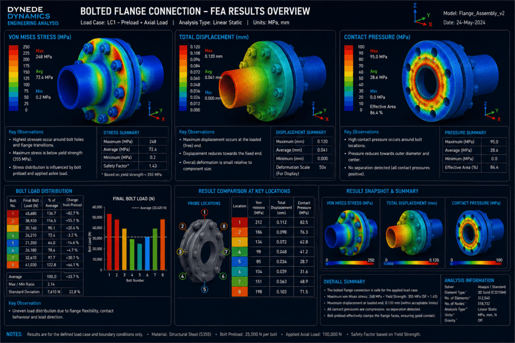
This finite element analysis study demonstrates the structural assessment of a representative bolted flange connection, with particular attention to bolt loading, contact behaviour, flange deformation and local stress distribution.
The objective is to understand how the complete joint responds under load and identify regions requiring detailed engineering assessment.
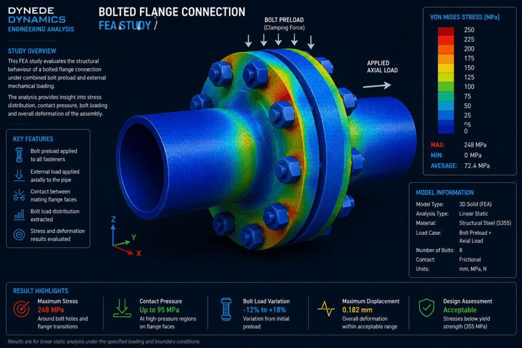
Engineering Challenge
A bolted flange connection relies on several interacting components to transfer load effectively.
Bolt preload clamps the mating surfaces together, while externally applied loads may change the contact pressure between the flange faces and alter the forces carried by individual bolts.
The engineering challenge is therefore to assess the behaviour of the connection as a complete assembly rather than considering the bolts and flange components independently.
The assessment considers:
- Bolt preload and clamping force
- External mechanical loading
- Contact between mating flange surfaces
- Load distribution between bolts
- Local stresses around bolt holes
- Flange bending and deformation
- Potential separation of mating surfaces
Finite element analysis provides a practical method of examining these interacting effects within a single structural model.
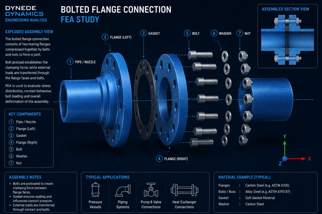
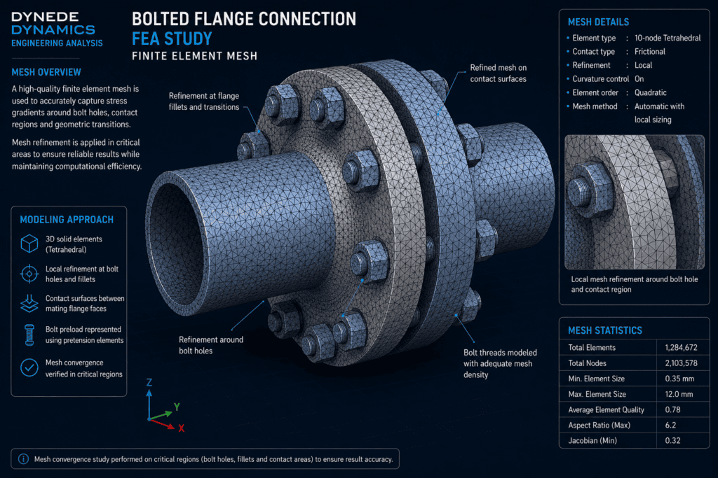
FEA Model Development
A three-dimensional finite element model is developed to represent the flange components, bolts and relevant contact interfaces.
The model includes the principal geometric features that influence stiffness and load transfer while avoiding unnecessary detail that would increase computational effort without improving the engineering assessment.
Particular attention is given to the bolt holes, flange transitions and mating surfaces because these regions can experience significant stress gradients and contact effects.
The model considers:
- Representative flange geometry
- Bolt and fastener locations
- Appropriate material properties
- Contact between mating surfaces
- Bolt preload representation
- Applied mechanical loading
- Suitable support conditions
- Local mesh refinement around critical features
Mesh refinement is concentrated around bolt holes, contact regions and geometric transitions where higher stress gradients are expected.
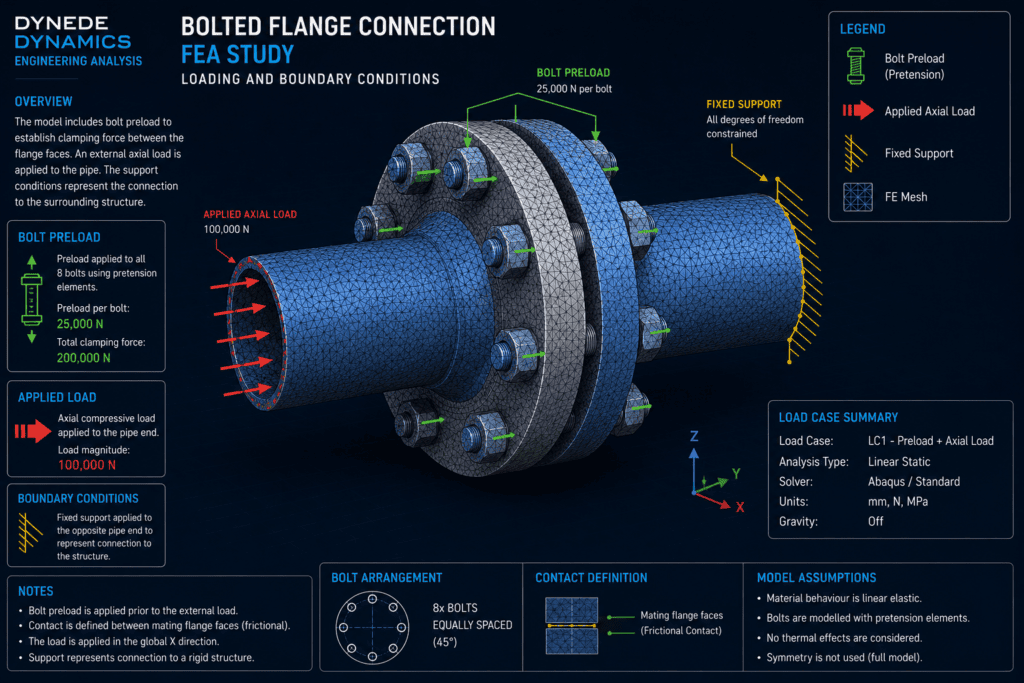
Loading and Boundary Conditions
Appropriate loading and boundary conditions are essential for representing the behaviour of the joint realistically.
Bolt preload establishes the initial clamping force between the mating components. External forces and moments can then modify the load distribution across the connection and change the contact pressure between the flange faces.
Depending on the application, loading may include axial force, bending moment, shear force or a combination of these effects.
Boundary conditions are selected to represent the surrounding structure while avoiding unnecessary restraint of the flange itself.
The resulting model allows the interaction between bolt forces, flange stiffness and external loading to be examined.
Contact Behaviour
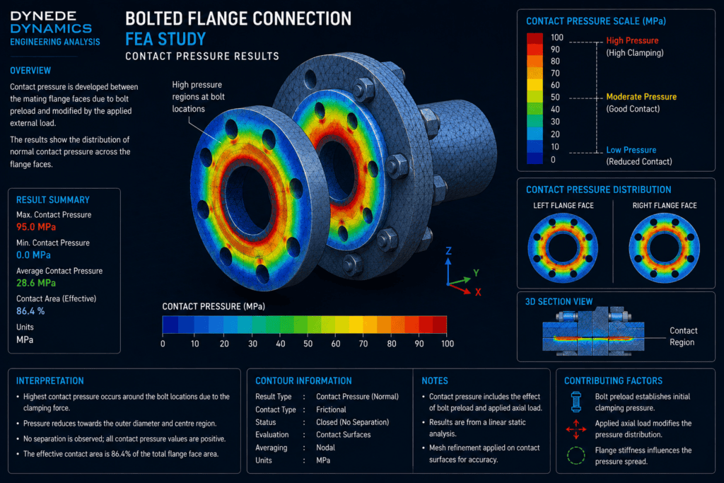
Contact between the mating flange surfaces is an important part of the structural behaviour of the connection.
Under bolt preload, the flange faces are compressed together. As external loading is applied, the contact pressure may become non-uniform and some regions may experience reduced compression.
The FEA model can be used to examine the distribution of contact pressure across the joint and identify areas where the mating surfaces remain firmly engaged.
This provides useful insight into how effectively the clamping force is distributed through the connection.
Stress Distribution
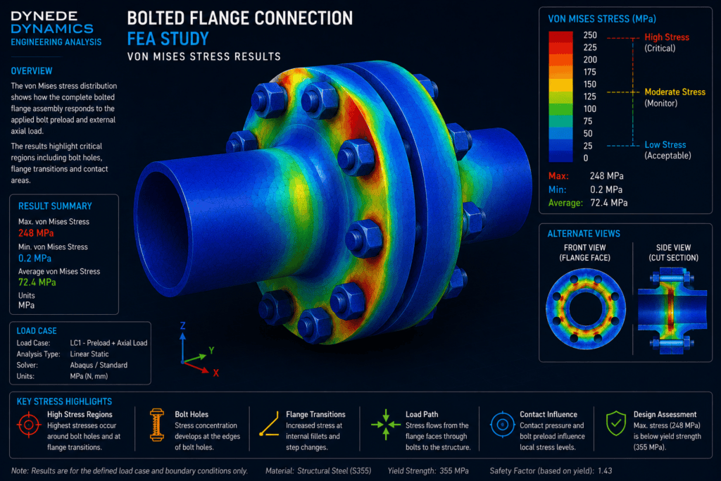
The FEA results provide a detailed view of the stress distribution throughout the flange, bolts and surrounding structural features.
Elevated stresses may occur around bolt holes, flange transitions and other regions where the load path changes rapidly.
Rather than relying solely on the maximum contour value, the stress field should be reviewed to determine whether elevated values represent meaningful structural behaviour or highly localised effects associated with geometry and modelling assumptions.
The overall stress pattern provides a clearer understanding of how the applied load is transferred through the connection.
Bolt Load Assessment
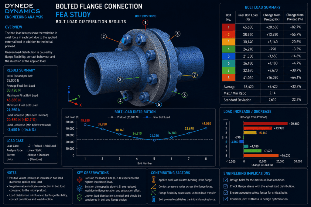
One of the principal advantages of modelling the complete connection is the ability to examine how the applied loading is distributed between the individual bolts.
Depending on the direction and magnitude of external loading, some bolts may experience a greater increase in load than others.
The analysis can therefore be used to examine:
- Relative bolt loading
- Changes from the initial preload condition
- Influence of flange deformation
- Load distribution across the bolt pattern
- Interaction between bolt forces and flange contact
This provides a more complete understanding of joint behaviour than treating every bolt as carrying an identical proportion of the applied load.
Displacement Assessment
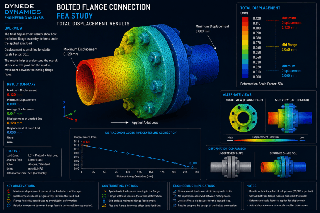
Displacement results show how the flange assembly deforms under the applied loading.
The deformation pattern can be reviewed to determine whether the joint behaves as expected and whether local flange flexibility significantly influences the connection.
Particular attention can be given to relative movement between the mating components and deformation around the loaded regions.
Reviewing displacement alongside stress and contact pressure provides a more complete picture of the structural response.
Engineering Interpretation
FEA results require engineering interpretation rather than simply reading maximum values from contour plots.
Stress, displacement, bolt loading and contact pressure should be considered together to understand the behaviour of the complete connection.
The analysis can help identify whether the principal structural response is associated with flange bending, local stress concentration, bolt loading or changes in contact between the mating surfaces.
This allows areas requiring further investigation to be identified efficiently and provides a technical basis for subsequent design decisions.
Engineering Outcome
The study demonstrates how finite element analysis can provide detailed insight into the behaviour of a bolted mechanical connection.
By modelling the interaction between the flange components, bolts and contact surfaces, the analysis provides information that may be difficult to obtain from simplified calculations alone.
A well-developed FEA model can help engineers:
- Understand load transfer through the joint
- Assess flange stress and deformation
- Examine bolt-load distribution
- Evaluate contact pressure
- Identify critical structural regions
- Investigate potential joint separation
- Support engineering design verification
- Produce clear technical documentation
The result is a better understanding of how the complete connection responds under representative mechanical loading.
FEA for Bolted Connections and Mechanical Assemblies
Dynede Dynamics provides finite element analysis for mechanical components, bolted connections, supports, structural assemblies and other mechanically loaded equipment.
FEA can be used during design development or as part of a detailed engineering assessment where local stresses, deformation, contact behaviour or load transfer require investigation.
Typical capabilities include:
- Linear static finite element analysis
- Contact analysis
- Bolt preload representation
- Stress and deformation assessment
- Local stress investigation
- Mesh refinement and convergence studies
- Load-path assessment
- Mechanical connection assessment
- Engineering interpretation of analysis results
- Technical reporting and documentation
Discuss Your Engineering Requirements
If you require finite element analysis of a bolted connection, flange, mechanical assembly or other loaded component, Dynede Dynamics can provide FEA support from model development and loading definition through analysis, interpretation and technical reporting.
To discuss your FEA requirements or a specific engineering challenge, please [contact Dynede Dynamics].