
Thermal-Fluid Assessment of a Shell-and-Tube Heat Exchanger
Shell-and-tube heat exchangers are widely used throughout process, energy, chemical and industrial systems to transfer thermal energy between two physically separated fluid streams. Although the basic operating principle is straightforward, the internal flow behaviour can become highly three-dimensional as the shell-side fluid interacts with the tube bundle, baffles, shell walls and inlet and outlet regions.
Computational Fluid Dynamics (CFD) provides a means of examining these internal flow and thermal characteristics in considerably greater detail than can be obtained from overall inlet and outlet conditions alone. Velocity distribution, recirculation, bypassing and temperature development can be visualised throughout the exchanger, allowing the influence of the internal geometry to be assessed.
This study considers a representative 1-shell-pass / 2-tube-pass shell-and-tube heat exchanger. The analysis focuses primarily on shell-side flow distribution and thermal behaviour while maintaining the two fluid circuits as separate domains coupled through heat transfer across the tube walls.
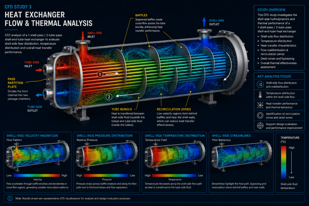
Cutaway 1-shell-pass / 2-tube-pass shell-and-tube heat exchanger showing shell-side CFD flow and thermal behaviour, tube-side flow direction, baffles and pass partition
Project Overview
The heat exchanger consists of a cylindrical shell containing a tube bundle supported and directed by a series of segmental baffles. A separate channel at the front of the exchanger is divided by a pass-partition plate to create the two tube-side passes.
Tube-side fluid enters one section of the front channel and flows through the first group of tubes towards the rear of the exchanger. The flow reverses within the rear return region and travels back through the second group of tubes before leaving through the tube-side outlet.
The shell-side fluid follows an independent path. It enters through the shell nozzle and is directed repeatedly across the tube bundle by the segmental baffles before leaving through the shell-side outlet.
The two fluids therefore remain physically separated while thermal energy is transferred through the tube walls.
Analysis Objectives
The principal objective of the CFD study is to investigate how the exchanger geometry influences flow distribution and thermal behaviour.
The assessment considers:
- Shell-side velocity distribution through the exchanger
- Cross-flow through successive baffle windows
- Flow maldistribution within the shell
- Recirculation and relatively low-velocity regions
- Bypassing near the shell and bundle boundaries
- Temperature development along the exchanger
- Interaction between fluid distribution and heat-transfer performance
- Regions that may benefit from geometric or baffle optimisation
The intention is not simply to produce temperature contours, but to understand why different parts of the exchanger experience different flow and thermal conditions.
CFD Model Development
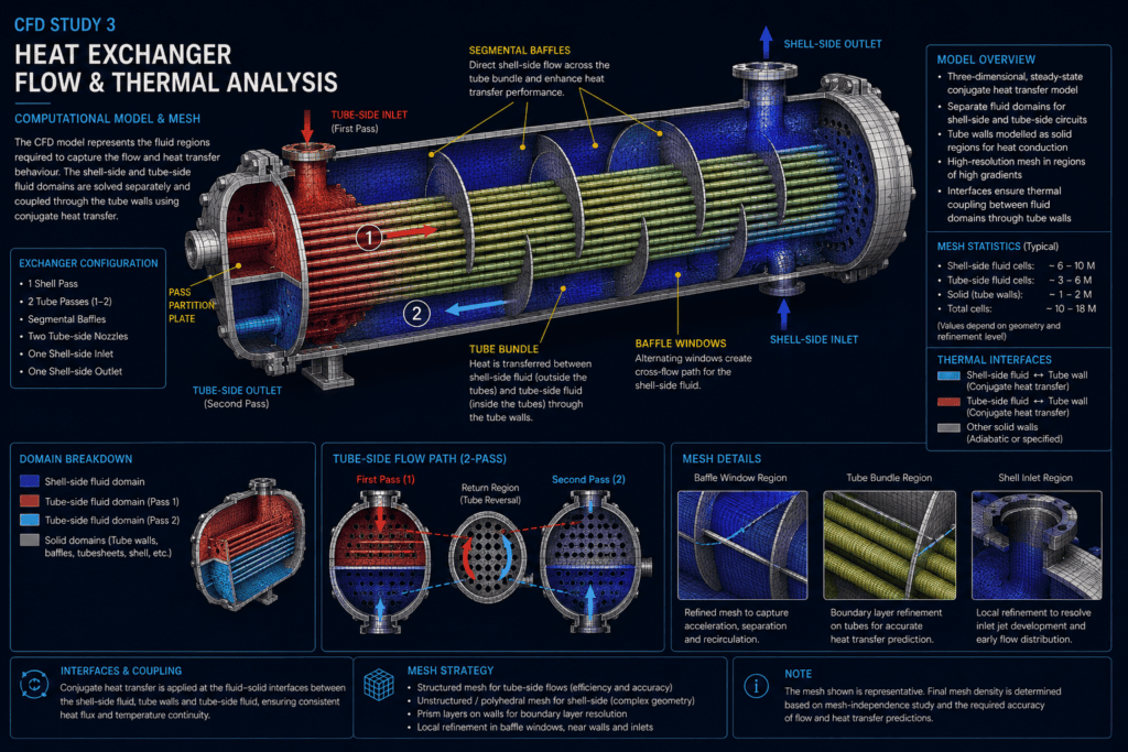
The CFD model represents the fluid regions required to describe the heat-transfer process rather than treating the exchanger as a single homogeneous volume.
Separate computational domains are established for the shell-side fluid and tube-side fluid. The tube walls form the physical boundary between these domains and provide the thermal path through which energy is transferred.
The tube bundle, tubesheets, shell and baffle arrangement are represented sufficiently to capture the principal flow mechanisms. Details that have negligible influence on the fluid behaviour may be simplified where appropriate to avoid unnecessary computational expense.
For the two-pass tube arrangement, the front channel is separated by a pass-partition plate. This ensures that the incoming tube-side fluid is directed through the first tube pass, reverses at the opposite end and returns through the second pass before reaching the outlet.
This distinction is important because the shell-side and tube-side flow paths must remain physically consistent with the actual exchanger configuration.
Boundary Conditions & Thermal Coupling
Separate inlet and outlet conditions are defined for the shell-side and tube-side circuits.
The shell-side inlet establishes flow into the shell, after which the baffles repeatedly redirect the fluid across the tube bundle. The shell-side outlet provides the downstream boundary after the fluid has passed through the baffled region.
The tube-side inlet supplies the first pass of the tube bundle. Following reversal in the return channel, the fluid travels through the second pass and exits through the separate tube-side outlet.
Solid surfaces exposed to the fluids are treated using appropriate wall conditions. Thermal coupling through the tube walls allows heat to pass between the two fluid streams while preventing mass transfer between them.
In a project-specific analysis, inlet temperatures, flow rates, pressures and thermophysical properties would be obtained from the actual process conditions. No specific plant-performance values are assumed for this illustrative study.
Mesh Strategy
A suitable CFD mesh is required to capture both the large-scale shell-side circulation and the smaller flow structures generated around the tubes and baffles.
Local refinement is particularly important around the baffle windows, tube bundle, shell inlet and outlet regions, where significant changes in velocity direction and magnitude can occur. These areas may contain comparatively steep velocity and temperature gradients.
Near-wall treatment must also be selected appropriately for the turbulence model and the level of heat-transfer prediction required.
The tube-side passages require sufficient resolution to represent the two flow passes and thermal interaction with the tube walls without introducing unnecessary mesh density in regions where the solution varies relatively smoothly.
Mesh quality and independence should be considered when quantitative performance predictions are required.
Shell-Side Flow Distribution
The segmental baffles play an important role in determining shell-side behaviour.
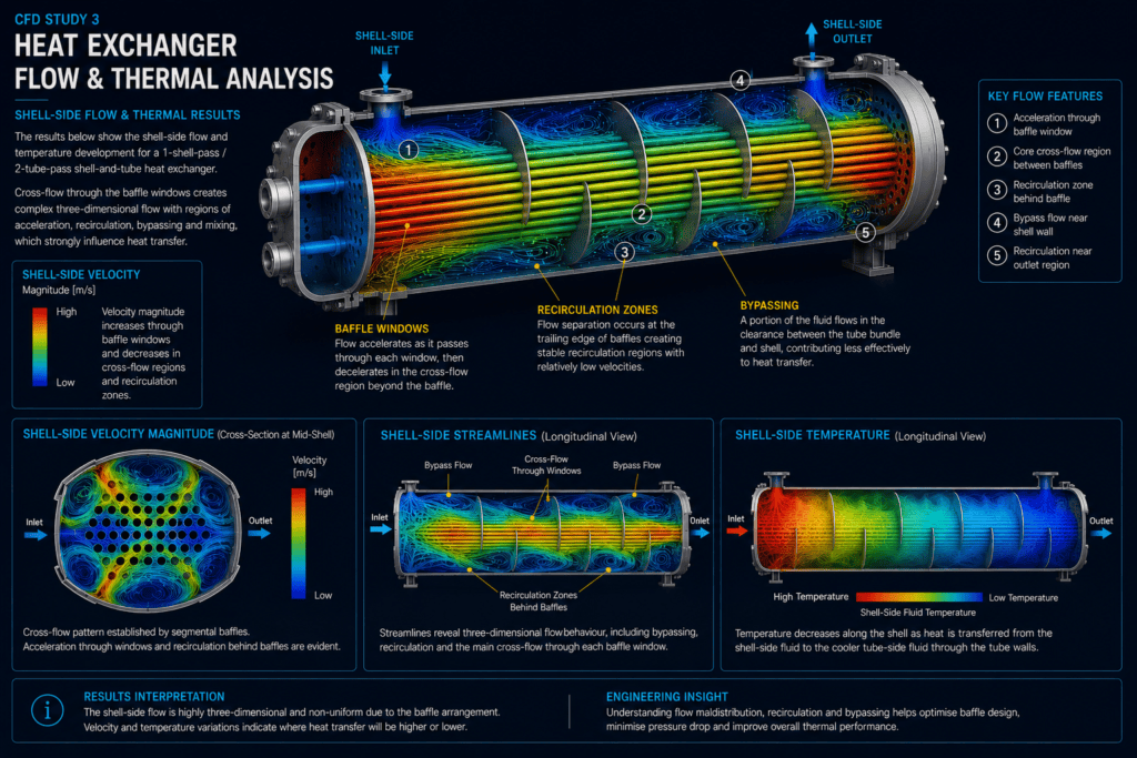
Rather than allowing the fluid to travel directly from inlet to outlet, the baffles force it repeatedly across the tube bundle. The resulting cross-flow increases interaction between the shell-side fluid and tube surfaces and can improve heat-transfer performance.
However, the flow field is not uniform. Fluid accelerates as it passes through restricted baffle-window regions and redistributes as it enters the larger cross-flow zones between adjacent baffles.
Changes in direction can also generate separation and recirculation behind baffles and close to other geometric discontinuities.
The CFD velocity field allows these variations to be examined throughout the complete shell rather than inferred from an average shell-side velocity.
Recirculation, Bypassing & Maldistribution
Not all shell-side fluid follows an ideal cross-flow path.
Local geometry can produce relatively low-velocity regions behind baffles and near the shell boundaries. Other portions of the flow may preferentially follow lower-resistance paths, resulting in bypassing or unequal distribution across different parts of the tube bundle.
These effects are significant because regions receiving comparatively little shell-side flow may contribute less effectively to heat transfer, while locally accelerated regions can produce larger pressure losses.
Streamline visualisation provides a useful means of identifying these flow structures and understanding how the baffle arrangement controls movement through the exchanger.
Temperature Distribution & Heat Transfer
The thermal solution shows how temperature develops as the two fluid streams exchange energy through the tube walls.
Unlike an idealised one-dimensional representation, the CFD model can reveal temperature variations both along and across the exchanger. These variations arise because the local thermal behaviour is influenced by the actual fluid distribution around individual regions of the tube bundle.
Areas experiencing strong shell-side circulation may exhibit different thermal behaviour from recirculating or bypass regions. Consequently, the temperature field and velocity field should be interpreted together.
The analysis can therefore identify not only where temperature changes occur, but also the flow mechanisms responsible for the observed thermal distribution.
Pressure Distribution
Pressure loss is another important aspect of shell-and-tube heat-exchanger performance.
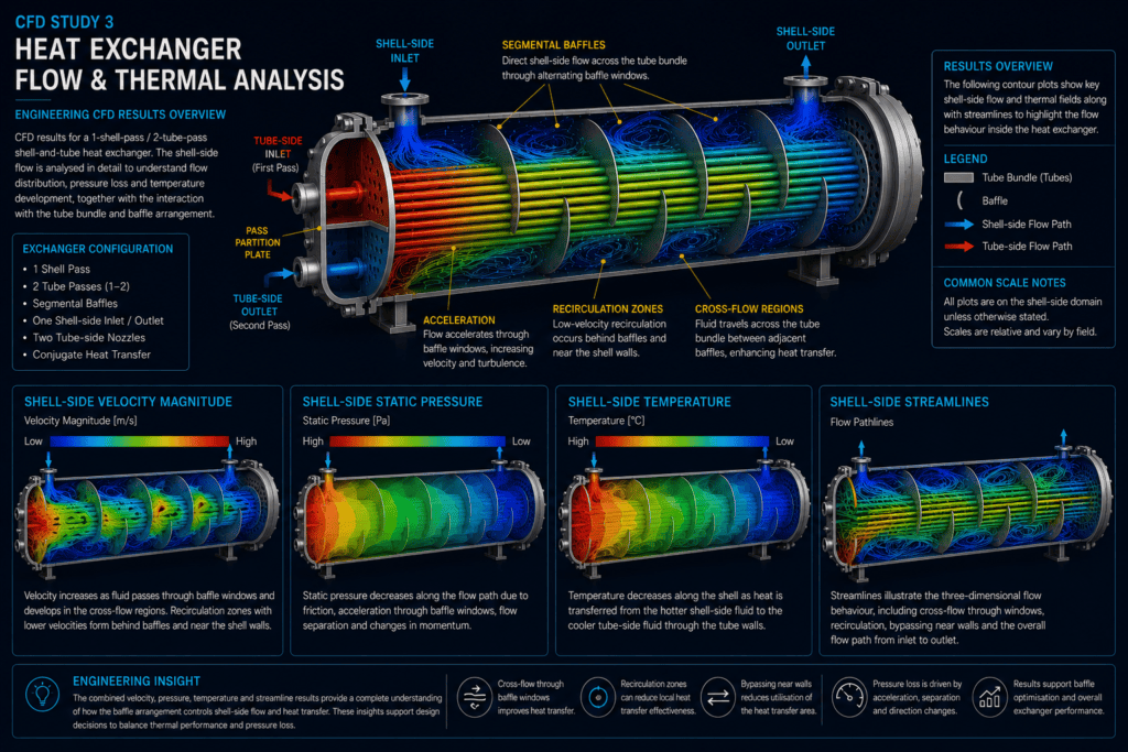
As the shell-side fluid moves through the exchanger, energy is dissipated through wall friction, repeated changes in direction, acceleration through baffle windows, flow separation and mixing.
The static-pressure solution can be examined to determine where significant portions of the overall pressure loss develop.
This is particularly useful during design development because increasing shell-side mixing can improve heat transfer while simultaneously increasing hydraulic resistance. The exchanger therefore needs to be assessed as a thermal-fluid system rather than optimised for heat transfer or pressure loss independently.
Engineering Interpretation
The CFD results demonstrate the close relationship between baffle arrangement, fluid distribution, pressure loss and thermal performance.
A design that produces strong cross-flow over the tube bundle may provide favourable heat-transfer behaviour but may also impose a larger pressure penalty. Conversely, excessive bypassing or large low-velocity regions can reduce the effective use of available heat-transfer surface.
CFD can therefore support engineering decisions involving:
- Baffle spacing and orientation
- Baffle cut and window geometry
- Shell-side inlet and outlet arrangement
- Tube-bundle configuration
- Flow maldistribution
- Reduction of undesirable recirculation or bypassing
- Thermal utilisation of the tube bundle
- Pressure-loss management
- Comparison of alternative exchanger configurations
The most appropriate configuration depends on the required thermal duty, allowable pressure loss, operating conditions, manufacturing constraints and applicable design requirements.
Engineering Results Overview
Velocity, pressure, temperature and streamline results provide complementary information about exchanger performance.
Velocity contours indicate how the shell-side fluid accelerates and redistributes through successive baffle regions. Pressure results illustrate the hydraulic penalty associated with moving the fluid through the exchanger. Temperature contours show the development of the thermal field, while streamlines reveal the three-dimensional paths responsible for recirculation, bypassing and maldistribution.
Considered together, these results provide a more complete assessment than any single contour plot or overall inlet-to-outlet value.
Engineering Considerations
The accuracy of a heat-exchanger CFD model depends strongly on the assumptions and numerical methods used.
Fluid properties should represent the relevant operating temperature range, and appropriate turbulence and thermal models should be selected. Mesh sensitivity, near-wall resolution and numerical convergence require particular attention where quantitative heat-transfer coefficients or pressure losses are required.
Real exchangers may also contain clearances between the bundle, baffles, tubes and shell that influence bypass and leakage flows. Depending on the objective of the study, these details may need to be represented explicitly.
For detailed design work, numerical predictions may also be compared with thermal-design calculations, empirical correlations, manufacturer information, test data or applicable industry design methods.
Outcome & Next Steps
This study demonstrates how CFD can be used to examine the coupled hydraulic and thermal behaviour of a shell-and-tube heat exchanger.
By resolving the internal flow field, the analysis provides insight into cross-flow through the baffles, local acceleration, recirculation, bypassing, pressure loss and temperature development. These results can help identify whether the available heat-transfer surface is being used effectively and where geometric changes could improve overall performance.
Further investigation could include alternative baffle spacing or cuts, different tube arrangements, modified inlet configurations, multiple operating conditions or comparison of candidate exchanger geometries.
The same methodology can also be extended to other thermal-fluid equipment where flow distribution and heat transfer are strongly coupled.
Discuss Your Engineering Requirements
Dynede Dynamics provides CFD analysis for heat exchangers, piping systems, valves and other thermal-fluid equipment, including computational-domain development, meshing, conjugate heat-transfer modelling, flow-distribution assessment and engineering interpretation of numerical results.
Discuss your CFD and thermal-analysis requirements with Dynede Dynamics to determine an appropriate modelling approach for your application.