
Project Overview
This computational fluid dynamics study examines internal flow through a 90-degree pipe elbow and the changes in velocity, pressure and flow structure produced as the fluid passes through the bend.
Although a pipe elbow is a relatively simple component, the change in flow direction introduces important three-dimensional effects. Fluid momentum causes the velocity distribution to become asymmetric through the bend, while pressure gradients across the elbow can generate secondary flow structures downstream.
The study demonstrates how CFD can be used to visualise these effects and provide engineering insight beyond that available from simple one-dimensional pressure-loss calculations.
The objective is to examine the development of the flow through the elbow, identify regions of acceleration and separation, and assess how the bend influences downstream flow behaviour.
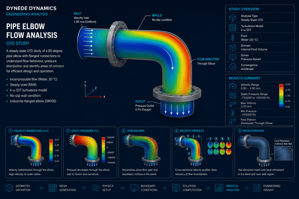
(90-degree pipe elbow with CFD velocity streamlines and contour)
Engineering Challenge
When fluid enters a curved pipe section, its direction must change while momentum carries the flow towards the outside of the bend.
This produces a pressure gradient across the elbow and redistributes the velocity profile. Higher momentum fluid tends to move towards the outer radius, while lower velocity regions may develop near the inner radius.
The resulting flow can contain:
- Non-uniform velocity distribution
- Pressure variation across the bend
- Secondary flow structures
- Local flow acceleration
- Low-velocity regions
- Possible separation near the inner radius
- Increased turbulence
- Downstream flow distortion
Understanding these effects is important because elbow-generated disturbances can influence pressure losses, vibration, erosion, downstream instrumentation and the performance of connected equipment.
CFD Model Development
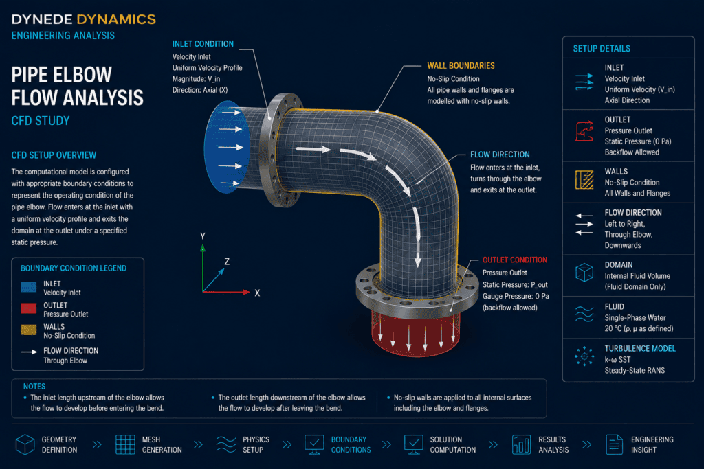
A three-dimensional computational domain is developed to represent the internal fluid volume of the pipe and 90-degree elbow.
Straight inlet and outlet sections are included so that the flow can develop before entering the bend and its downstream behaviour can be examined after leaving the elbow.
The CFD model considers:
- Representative pipe diameter
- 90-degree elbow geometry
- Straight inlet section
- Straight downstream section
- Fluid properties
- Inlet flow condition
- Outlet pressure condition
- No-slip pipe walls
- Appropriate turbulence treatment
- Local mesh refinement through the bend
The purpose of the model is to reproduce the principal flow behaviour sufficiently accurately for meaningful engineering interpretation.
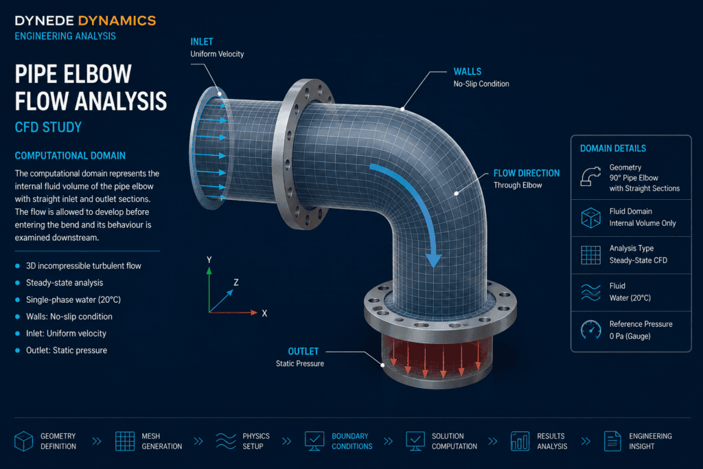
Mesh Development
Mesh quality is particularly important through the elbow because the flow direction changes rapidly and significant velocity and pressure gradients can develop across the bend.
The computational mesh is therefore refined within the curved region and near the pipe walls where stronger gradients are expected.
Additional attention can be given to the near-wall region where appropriate to the turbulence modelling approach.
A suitable mesh should capture the main flow structures without introducing unnecessary computational cost throughout regions where the solution varies more gradually.
Mesh refinement may therefore concentrate on:
- Inner and outer bend surfaces
- Near-wall regions
- Areas of rapid velocity change
- Regions susceptible to separation
- Downstream flow-development region
Mesh sensitivity can be assessed where greater confidence in the numerical results is required.
Boundary Conditions
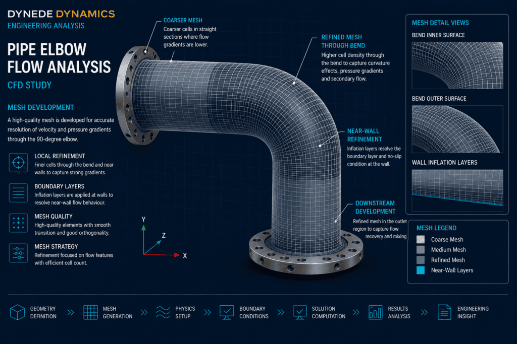
Appropriate boundary conditions are required to reproduce the intended operating condition of the pipe system.
A representative inlet flow condition is applied upstream of the elbow, while the downstream boundary allows the flow to leave the computational domain without artificially disturbing the bend region.
The pipe walls are represented using no-slip conditions so that the velocity reduces towards the solid surfaces.
The analysis therefore establishes a controlled numerical environment in which the effect of the elbow geometry on the internal flow can be investigated independently.
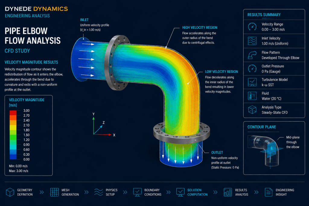
Velocity Distribution
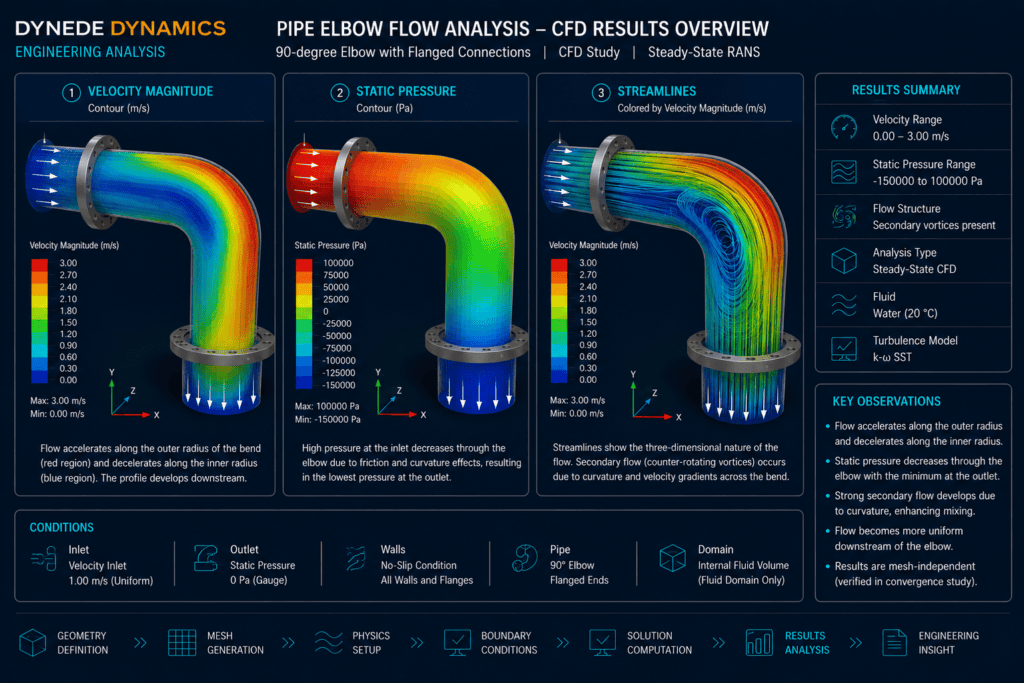
The velocity field provides one of the clearest indications of how the elbow influences the flow.
As the fluid enters the bend, the velocity profile becomes increasingly asymmetric. Momentum carries higher-velocity fluid towards the outer radius while the inner region may experience lower velocity and stronger gradients.
The resulting velocity distribution can remain distorted after the fluid leaves the elbow.
CFD allows this behaviour to be examined throughout the complete flow domain rather than only at individual measurement locations.
The velocity results can be used to identify:
- High-velocity regions
- Low-velocity regions
- Flow acceleration
- Downstream velocity distortion
- Areas of strong velocity gradient
- Potential regions of recirculation
Pressure Distribution
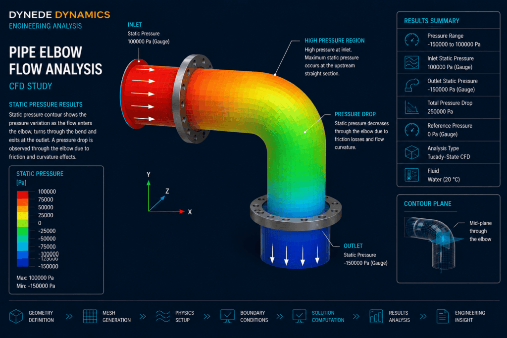
The change in flow direction also produces a characteristic pressure distribution through the elbow.
Pressure tends to vary between the inner and outer regions of the bend as the fluid is forced to follow the curved flow path.
The analysis can therefore be used to examine both the local pressure field through the elbow and the overall pressure change between upstream and downstream sections.
This is particularly useful when evaluating components where pressure loss contributes to pumping requirements or overall system performance.
Rather than relying only on a single pressure-drop value, CFD shows where and how the pressure changes occur within the component.
Secondary Flow & Streamlines
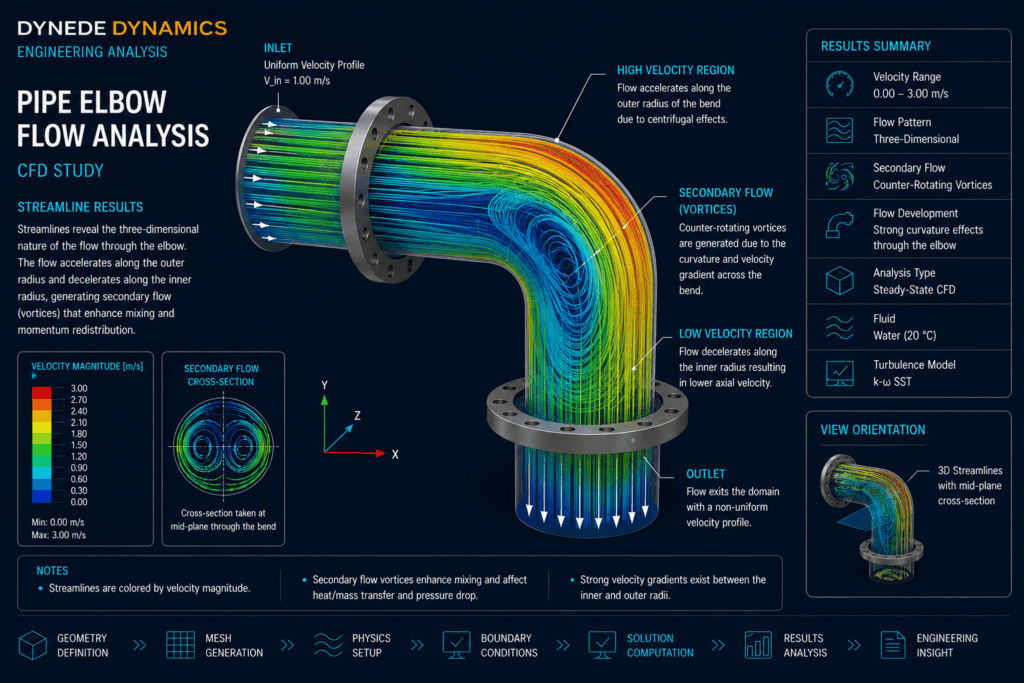
One of the most useful aspects of a three-dimensional CFD analysis is the ability to visualise flow structures that cannot be represented adequately by a simple two-dimensional velocity profile.
Curvature of the elbow can produce secondary motion across the pipe cross-section as the fluid responds to the pressure gradient generated through the bend.
Streamlines provide an intuitive way of visualising the resulting three-dimensional flow path.
They can reveal:
- Redistribution of the main flow
- Secondary circulation
- Flow curvature
- Low-momentum regions
- Downstream disturbance
- Potential recirculation zones
These structures help explain why the velocity profile downstream of an elbow may differ substantially from the profile entering it.
Downstream Flow Development
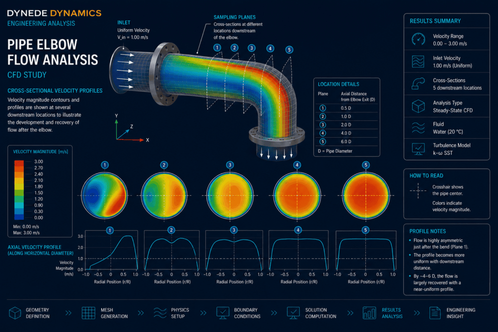
The effect of the elbow does not end immediately at the outlet of the bend.
The distorted velocity field continues into the downstream pipe and gradually develops as momentum is redistributed across the cross-section.
This can be important where flow-sensitive equipment is positioned close to an elbow.
Flow meters, valves, heat exchangers, branches and other downstream components may experience a significantly different inlet condition depending on their distance from the bend.
CFD provides a practical method of examining this downstream development and determining whether significant flow non-uniformity remains within the region of interest.
Engineering Interpretation
The value of the CFD analysis is not simply the production of colourful contour plots.
The results provide a physical explanation of how the component geometry affects the fluid.
For the pipe elbow, the analysis demonstrates the relationship between:
- Flow curvature
- Momentum redistribution
- Pressure gradients
- Secondary flow
- Velocity-profile distortion
- Downstream recovery
Understanding these relationships allows engineers to interpret the behaviour of the component and assess its potential influence on the wider piping system.
The same methodology can be extended to more complex piping geometries where analytical methods alone cannot adequately describe the three-dimensional flow behaviour.
Engineering Outcome
The study demonstrates how computational fluid dynamics can provide detailed insight into internal flow through a pipe elbow.
By examining velocity, pressure and flow structure together, the analysis provides a more complete understanding of the component than a pressure-loss calculation alone.
A well-developed CFD model can help engineers:
- Visualise internal flow behaviour
- Identify regions of high and low velocity
- Examine pressure distribution
- Investigate secondary flow
- Identify potential recirculation
- Assess downstream flow distortion
- Understand component pressure losses
- Support engineering design decisions
The resulting information can support the assessment of piping components and provide a basis for more detailed investigation where required.
CFD Analysis for Internal Flow Systems
Dynede Dynamics provides computational fluid dynamics analysis for mechanical components and internal flow systems.
CFD can be integrated with mechanical design and engineering analysis to investigate fluid behaviour before components are manufactured or modified.
Typical capabilities include:
- Internal flow analysis
- Velocity and pressure assessment
- Pressure-loss investigation
- Flow-distribution analysis
- Streamline visualisation
- Recirculation assessment
- Turbulent-flow analysis
- Mesh refinement studies
- Design comparison
- Engineering interpretation of CFD results
- Technical reporting and documentation
Discuss Your Engineering Requirements
If you require CFD analysis of a pipe system, elbow, valve, manifold or other internal-flow component, Dynede Dynamics can provide engineering support from computational model development and boundary-condition definition through analysis, interpretation and technical reporting.
To discuss your CFD requirements or a specific flow problem, please contact Dynede Dynamics.