
Structural Weight Reduction Through Topology Optimisation
Reducing component mass without compromising structural performance is an important objective in many mechanical engineering applications. Traditional weight-reduction methods often rely on progressively removing material from an existing design, but this approach may not identify the most efficient load paths within the available design space.
Topology optimisation provides a more systematic method. Loads, supports, design constraints and regions that must remain unchanged are defined first, allowing the optimisation process to determine where material contributes most effectively to the structural response.
This study demonstrates a representative topology-optimisation workflow for a structural mounting bracket. The process begins with a conventional baseline geometry, identifies an efficient material distribution, develops the resulting topology into a practical CAD model and finally verifies the reconstructed component using finite element analysis.
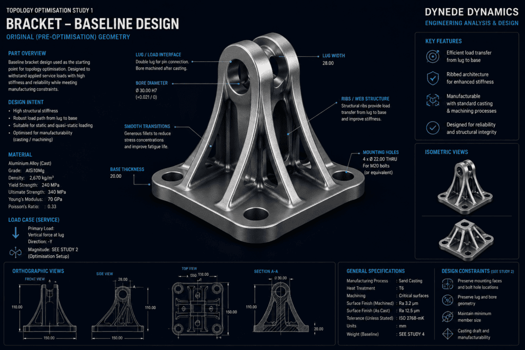
The original structural bracket, topology-optimisation density result and reconstructed optimised design with comparative FEA results
Project Overview
The starting point is a conventional structural bracket consisting of a mounting base, fixing locations and an upper load-transfer feature connected through supporting ribs.
The original component provides a clear and robust load path, but portions of the available material may make relatively little contribution to the required structural behaviour.
The objective of the study is therefore not simply to remove material. It is to determine where material is structurally necessary, preserve the important load paths and develop a lighter geometry capable of performing the same engineering function.
The workflow consists of four principal stages:
- Definition of the optimisation problem
- Topology optimisation and material-distribution assessment
- Reconstruction of the resulting geometry
- Structural validation of the optimised design
This distinction is important because the raw topology result is an engineering optimisation output rather than a finished component ready for manufacture.
Baseline Structural Model
Before optimisation begins, the original component is assessed using finite element analysis.
The baseline model establishes the structural response of the conventional design under the representative loading condition. Appropriate supports are applied at the mounting locations, while the service load is introduced through the load-transfer region of the bracket.
The analysis provides a reference for subsequent comparison with the optimised design.
Particular attention is given to the principal load paths between the loaded region and the mounting points, together with areas of stress concentration and regions carrying comparatively little structural load.
The baseline assessment therefore provides both a performance reference and an initial indication of where material may be used inefficiently.
Optimisation Setup
Topology optimisation requires the engineering problem to be defined before material removal begins.
The available component volume is established as the design space. Within this region, the optimisation process is permitted to redistribute or remove material.
Features that must remain unchanged are identified as non-design or preserved regions. These typically include mounting interfaces, bolt holes, bearing surfaces, load-application regions and other geometry required for assembly or functional reasons.
The representative loading and support conditions are then applied consistently with the baseline structural assessment.
The optimisation objective is to reduce structural mass while retaining the required mechanical behaviour and preserving the essential interfaces of the component.
Practical constraints must also be considered because an unconstrained mathematical solution may produce geometry that is difficult or inappropriate to manufacture.
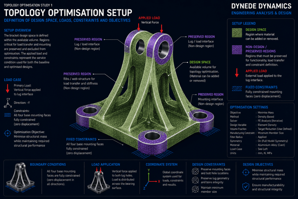
Material Distribution & Load Paths
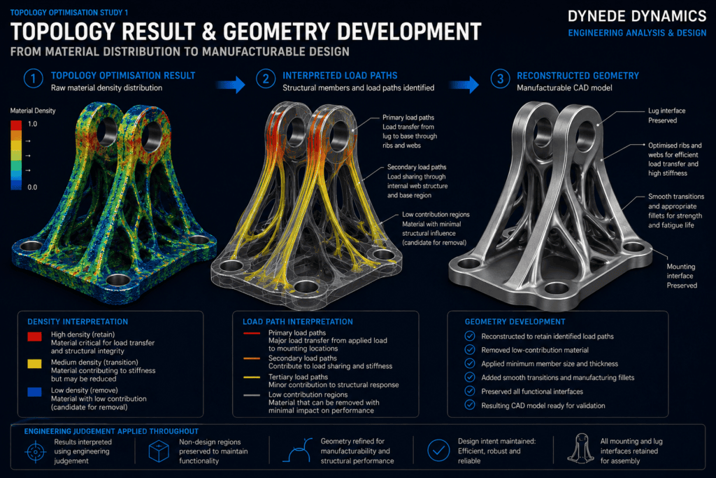
During topology optimisation, the available design space is evaluated according to its contribution to the structural objective.
Regions that form important load paths are retained, while material with comparatively little structural influence can progressively become a candidate for removal.
The resulting material-density distribution provides a visual representation of the structural paths connecting the applied load to the constrained mounting regions.
This can produce an organic-looking form that differs considerably from a traditionally designed bracket. Such shapes arise because the optimisation process is responding primarily to the structural problem rather than conventional geometric expectations.
The result should therefore be interpreted as a guide to efficient material placement, not automatically accepted as the final component geometry.
Interpreting the Topology Result
Engineering judgement becomes particularly important after the optimisation calculation is complete.
Very thin members, irregular surfaces, small isolated features or difficult internal transitions may appear in the raw result. These features may not be desirable from a manufacturing, durability or inspection perspective.
The topology result must therefore be reviewed to identify the dominant structural features that should be retained.
For the representative bracket, these include the principal members connecting the upper load-transfer region to the mounting points and the supporting geometry required to maintain stiffness through the base.
Material outside these important paths can then be reduced while maintaining smooth transitions between the remaining structural members.
Geometry Reconstruction
The optimised density field is subsequently converted into a practical engineering geometry.
Rather than simply smoothing the raw optimisation surface, the component is reconstructed as a controlled CAD model with defined surfaces, suitable radii and continuous structural members.
The reconstruction process considers:
- Preservation of mounting and load-transfer interfaces
- Continuity of the principal load paths
- Suitable member thickness
- Smooth geometric transitions
- Reduction of unnecessary stress raisers
- Accessibility of mounting features
- Practical manufacturing considerations
- Appropriate fillets and local reinforcement
The resulting geometry should retain the structural logic identified by the optimisation while being considerably more suitable for engineering manufacture and subsequent analysis.
Structural Validation
Topology optimisation alone does not demonstrate that the final reconstructed component satisfies its engineering requirements.
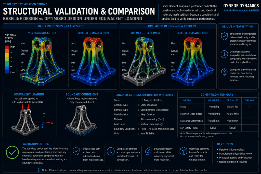
Once the new CAD geometry has been produced, it is analysed again using finite element analysis under the representative loading and constraint conditions.
The validation model allows the stress distribution, deformation and overall structural behaviour of the reconstructed component to be compared with the baseline design.
Areas affected by material removal require particular attention because reconstruction changes the geometry from the original topology result and may introduce local stress concentrations that were not apparent in the optimisation density field.
The final geometry may therefore require several iterations between CAD development and FEA validation before an acceptable balance between mass reduction and structural performance is achieved.
Stress Distribution
The stress field of the optimised component provides an indication of how effectively the reconstructed geometry transfers load through the remaining material.
Efficient optimisation does not necessarily mean producing uniform stress everywhere. Local geometry, interfaces and loading conditions naturally create variations in structural response.
Instead, the objective is to remove material that contributes little to the required behaviour while maintaining suitable load paths through the regions that remain.
Comparison with the original component helps determine whether material reduction has introduced unacceptable local behaviour or merely made more effective use of the available material.
Stiffness & Deformation
Weight reduction must also be considered in relation to stiffness.
A component may remain below an allowable stress while experiencing excessive deformation, potentially affecting alignment, assembly behaviour or the operation of connected equipment.
The displacement response of the optimised bracket is therefore assessed alongside stress.
Where necessary, material can be restored or redistributed to increase stiffness in critical regions without returning to the mass of the original conventional geometry.
This illustrates why topology optimisation is best treated as an iterative engineering design process rather than a one-step material-removal exercise.
Manufacturing Considerations
A mathematically efficient topology is not necessarily the most appropriate manufactured design.
The preferred geometry depends strongly on the intended manufacturing process. A component produced by machining, casting, forging or additive manufacturing may require very different geometric constraints.
Minimum member thickness, tool accessibility, draft requirements, build orientation, support requirements, surface finish and inspection access may all influence the final design.
Manufacturing considerations should therefore be introduced during the optimisation and reconstruction stages rather than considered only after the structural solution has been developed.
Original vs Optimised Design
The final engineering assessment compares the reconstructed component with the original baseline design.
The comparison considers the reduction in material together with changes in stress distribution, stiffness and overall structural behaviour.
The objective is not to claim the largest possible percentage reduction in mass. A useful engineering solution is one that provides a meaningful reduction while continuing to satisfy the functional, structural and manufacturing requirements of the component.
For this illustrative study, no specific mass-reduction percentage or allowable stress is claimed. These values would depend on the actual material, loading conditions, design constraints, manufacturing method and acceptance criteria associated with a real application.
Engineering Interpretation
Topology optimisation can reveal load paths that may not be immediately apparent from conventional design development.
However, the optimisation algorithm does not replace engineering judgement.
The resulting component must still be reviewed for realistic loading, fatigue-sensitive details, stress concentrations, stiffness, connections, manufacturing requirements and any applicable design criteria.
The greatest value of the method is therefore obtained by combining numerical optimisation, CAD development, FEA validation and engineering interpretation within a single iterative workflow.
This allows topology optimisation to become a practical design-development tool rather than simply a method of producing visually complex lightweight geometry.
Engineering Applications
The same methodology can be applied to many components where structural mass and material utilisation are important, including mounting brackets, machinery components, support structures, aerospace components, automotive parts and specialised equipment.
Depending on the application, optimisation objectives may extend beyond mass reduction to include stiffness, natural frequency, manufacturing constraints or other performance requirements.
The optimisation strategy should therefore be selected according to the actual engineering function of the component rather than applying a generic material-reduction target.
Outcome & Next Steps
This study demonstrates a complete topology-optimisation workflow from the original structural design through material-distribution analysis, CAD reconstruction and final FEA validation.
The process provides a systematic method of identifying structurally inefficient material while preserving the load paths required to transfer service loads through the component.
Further development could include additional load cases, fatigue assessment, manufacturing-specific optimisation constraints, modal analysis or comparison of alternative reconstructed geometries.
Where appropriate, the workflow can also be incorporated earlier in the design process so that structural efficiency influences the component architecture before the detailed geometry becomes fixed.
Discuss Your Engineering Requirements
Dynede Dynamics provides engineering design, finite element analysis and design-optimisation services for mechanical components and structural systems, including topology optimisation, geometry development and structural validation.
Discuss your design-optimisation requirements with Dynede Dynamics to determine an appropriate analysis and development approach for your application.